After more than 10 years offering the Infineon and then Grinfineon motor controllers we decided that our 2021 bulk order would be our last. These controllers played an important role in getting a wide range of ebike conversions on the road but challenges in supply, combined with an oudated form factor and limited feature set meant that they had run their course for us. They have been fully replaced by the Baserunner and Phaserunner controller series which pack an aweful lot more punch in a much smaller package. This page is being left up for legacy and support reasons.
The motor controllers we carry have been reworked and spec'd to be as universal as possible, so that can function with almost any small electric vehicle setup running a brushless DC motor. This makes them perfect for DIY and aftermarket builds. Some of the key features include:
At the moment we carry 2 versions with 100V IRFB4110 mosfets; a compact 6 transistor design with a 25A battery current limit, and a larger 12 mosfet board for up to 40 amps. The 40A units have a 29V low voltage cutoff and an 88V maximum regen voltage for 72V system compatibility. The 6 mosfet version, while in principle could handle 72V batteries, still has an upper voltage limit of 58V since most people with 52V or lower batteries and regen up to 88V could damage BMS circuits.
We also carry two less expensive controller options that use 60V components: a small 20 amp model, and a larger 12 mosfet 35A version. Up until 2016, these models worked down to a 19V cutoff allowing them to work with 24V batteries OK. But with the switch to the sinwewave circuitboad the minimum voltage had to be raised to 27V for the DC-DC circuit to function properly, so they now have a low voltage cutoff of 27V, allowing them to work with 36 to 52V nominal batteries. .
| |
Grinfineon 20A |
Grinfineon 25A |
Grinfineon 35A |
Grinfineon 40A |
| Battery Range |
36 - 52V |
36 - 52V |
36 - 52V |
36 - 72V |
| Current Limit |
20 Amps |
25 Amps |
35 Amps |
40 Amps |
| Low Voltage Cutoff |
27V |
27V |
27V |
31V |
| Waterproofing |
Good |
Good |
Good |
Good |
| Ebrake Function |
Regen to 58V |
Regen to 58V |
Regen to 58V |
Regen to 88V |
| Mosfets |
6x AOT460 |
6x IRFB4110 |
12x AOT460 |
12x IRFB4110 |
| Dimensions (mm) |
105 x 68 x 32 |
105 x 68 x 32 |
151 x 86 x 42 |
151 x 86 x 42 |
User Manuals
Sinewave Grinfineon User Manual, 25A, 35A, 40A Models (higher eRPM, no hall mapping)
Sinewave Grinfineon User Manual, 20A Model with Higo Plug, for Geared Motors
Sinewave Grinfineon User Manual, 20A Model with Thermistor Pass-thru for Brompton Kit
Original Grinfineon User Manual (2013-2016, auto hall mapping, non-sinewave)
FAQ on the Current Sinewave Grinfineon Controllers
Does the sensorless mode work on geared motors?
The answer to this is that it depends on the particular motor. In sensorless mode, the controllers have a safe upper commutation frequency limit of about 28000 electrical RPM. So with geared motors like the Bafang G01 hubs that have 50 or fewer commutations per revolution they work great, but those like the eZee with 80 commutations per revolution or the G310 at 88 can lose lock with high speed setups.
What is electrical RPM?
This would be the mechanical RPM, times the number of magnet pole pairs in the motor, times the gear ratio from the motor to the wheel. So for instance, a BMC motor has a 5:1 gear ratio, and 16 magnetic pole pairs. If the wheel is spinning at 300 RPM, then the controller is running at 300*16*5 = 24,000 eRPM. That would be no problem either sensored or sensorless. However, if the motor is run beyond 350 rpm, then the electrical commutation frequency is over 28,000 eRPM and the controller would need to be run sensored. It would not be able to acheive more than 350 rpm in sensorless mode with a motor that has 80 pole pairs.
What is the pinout for XYZ Motor?
The pinout for the controller matches colour for colour with both the standard eZee and Crysatlyte hub motors. For stock hub motors from Bafang and bafang clones, the required colour mapping is different. If the motor phase wires are matched colour for colour, then the hall pinout would be Controller Yellow to Motor Blue, Controller Blue to Motor Green, and Controller Green to Motor Yellow.
How many amps of regen will I get?
The regen current flowing through the motor is fairly constant, but the current returning back to the battery is then very dependant on your speed and voltage, with higher speeds resulting in more regen amps. The following graphs show the regenerative braking torque and current for the Grinfineon controllers at 0.0, 0.2, 0.4, and 0.6V throttle signal levels when tested with a Crown TC3080 motor.

My controller LED is flashing on and off, is that normal?
If the controller LED is flashing on and off in a steady rhythm, that means that it is running in sensorless mode and does not have a set of valid hall signals. When the hall sensors are plugged in and properly mapped, once the throttle is engaged, then the LED will either stay steady ON if it is running in sensored mode, or it will blink at a faster 2Hz rate if it is running sensorless. A repeated flash sequence followed by a pause indicates a status or fault condition.
Is the Controller Waterproof?
By and large, yes. The silicone grommets on either end do an excellent job keeping water out of the controller, and the toggle switch and LED are sealed in place as well. We recommend installing the controller in a location that gets good airflow and with the wire harness coming out either horizontally or downwards. Exposure to rain is not generally an issue.
Can I Reprogram the Controller Settings?
Unfortunately not, for reasons outside of our control these boards are not available to us in a way that is compatible with parameter designer software to change the settings. However, all the regular settings (low voltage cutoff, current limit, throttle auto-cruise and ramping etc) and much more can easily be done via the Cycle Analyst.
FAQ on the Original Grinfineon (2013-2016)
Does the sensorless mode work on geared motors?
The answer to this is that it depends on the particular motor. In sensorless mode, the controllers have a safe upper commutation frequency limit of about 13000 electrical RPM. So with geared motors like the Outrider hubs that have 50 or fewer commutations per revolution they work OK, but those like the eZee, MAC, and BMC with 80 commutations per revolution are prone to loosing lock and may require sensored mode.
What is electrical RPM?
This would be the mechanical RPM, times the number of magnet pole pairs in the motor, times the gear ratio from the motor to the wheel. So for instance, a BMC motor has a 5:1 gear ratio, and 16 magnetic pole pairs. If the wheel is spinning at 300 RPM, then the controller is running at 300*16*5 = 24,000 eRPM.
What is the pinout for XYZ Motor?
Because of the automatic hall mapping, there is no longer a fixed colour pinout between the controller and motor. The only variation that you need to know is that swapping any pair of the phase leads will reverse the direction of rotation.
How does this automatic hall mapping work?
In order to map a new hall pinout, it is important to first run the controller in sensorless mode by unplugging the hall connector and hitting the throttle. If the motor spins in reverse, swap a pair of the phase wires. Then connect the hall sensors and hit the throttle again. The motor will spin up to speed a bit slower than usual, and will automatically note the hall sequence. When the throttle is released and reapplied, it will now be operating in sensored mode.
How many amps of regen will I get?
The regen current flowing through the motor is fairly constant, but the current returning back to the battery is then very dependant on your speed and voltage, with higher speeds resulting in more regen amps. At the unloaded motor RPM, the regen current should be about 7 amps in standard, and 14 amps in high current mode. The following graph shows the measured regen current in each mode as a function of your speed, where 100% is the full unloaded speed of your particular motor/battery setup.
My controller LED is flashing on and off, is that normal?
Yes, for whatever reason a steady 0.8 second on/off flash means all systems are ready to go. Once the throttle is engaged, then then the LED will either stay steady ON if it is running in sensored mode, or it will blink at a faster 2Hz rate if it is running sensorless. A repeated flash sequence followed by a pause indicates a status or fault condition.
What are the other LED sequences?
There are 5 status flash codes indicating different modes of controller operation. Here the LED's will blink quickly a number of times and then pause:
1 Flash: Brake Cutoff Engaged
2 Flashes: Regenerative Braking has been Engaged
3 Flashes: Battery voltage is below the low voltage cutoff
4 Flashes: Controller shut off because motor had stalled
5 Flashes: Throttle voltage fault, or already high when controller powered on
If there is an actual controller fault, then the LED will stay on for a long time and only briefly turn off.
1 Flash: Motor Short Circuit Protection has Engaged
2 Flashes: 15V Regulator Circuit is Damaged
3 Flashes: Throttle Signal Fault (>4.2V)
5 Flashes: Microprocessor is damaged
Notice that there is no flash sequence for an invalid hall sequence (as happens when one signal is down) or when the controller loses lock in sensorless mode because the electrical RPM was too high. So in practice, the LED codes aren't all that useful in some key fault situations.
What is the Throttle Input Range?
The controller starts to respond 1.5V and reach full power at 3.5V, and then at 4.1V considers a fault. The 5V supply on the throttle plug flows passes through a diode so throttle chip is only powered by about 4.4V, and that's why the signal range is squished down a bit.
Notice too that there is a bit of a 'staircase' pattern between the input throttle voltage and the controller output. It turns out the throttle signal is being discretized into about 50 steps from 0 to max power. In most situations with a throttle control this is not very noticeable, but with higher power setups that use the CA's throttle limiting features, it can result in a 'rough' feeling as the controller is repeatedly jumping between two different output states rather than settling at the ideal value in between. The CA limiting still works, but not as nicely as we would like, and we are working to resolve this issue.
Is the Controller Waterproof?
By and large, yes. The silicone grommets on either end do an excellent job keeping water out of the controller, and the toggle switch and LED are sealed in place as well. We recommend installing the controller in a location that gets good airflow and with the wire harness coming out either horizontally or downwards. Exposure to rain is not generally an issue.
Can I Reprogram the Controller Settings?
Unfortunately not, for reasons outside of our control these boards are not available to us in a way that is compatible with parameter designer software to change the settings. However, all the regular settings (low voltage cutoff, current limit, throttle auto-cruise and ramping etc) and much more can easily be done via the Cycle Analyst.
Can the Controller run Sinusoidal Mode?
No. These controllers are trapezoidal drive devices which is still the standard for BLDC motor controllers. This scheme works great with a wide range of motor types, but you can often hear a little bit of motor buzz with them. Sinusoidal output controllers run most motors even more smoothly, at the expense of higher switching losses. For us the ability to operate both sensored AND sensorless is key, and the Infineon sinewave control chips available do not have this feature.
Will you have a Sinusoidal Controllers?
Yes, we are working with Accelerated Systems (ASI) of Toronto to bring an aftermarket field-oriented ebike controller into production that can run sensored and sensorless, among many other things. It will be a deluxe controller, and not very cheap. (Available now as the Phaserunner of course!)
FAQ on the pre-2013 Infineon
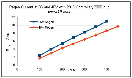
How do you configure the Infineon controller for Regen?
Since Feb 2010, all of our Infineon controllers have been supplied with regenerative braking already enabled by default. Simply plug in an ebrake lever to the 4-pin connector on the controller, and the controller will brake regeneratively when the lever is depressed and charge the battery in the process. The amount of regen torque is roughly constant, which means that the amount of regen current flowing back into the battery is a function of the speed at which you are travelling. If you are moving faster, the braking torque is the same, but you have more watts going into the battery because the power (torque*rpm) is greater. Similarly, with a higher voltage battery, the same power into the hub (Volts * Amps) equates to less current. The graph below shows the amount of regen current measured against wheel RPM with the 2806 winding hub.
While the regenerative braking can bring the bike to a stop reasonably fast, it has nowhere near the stopping power of fully applied mechanical brakes, which should always be available for emergency stops. To disable regen and have the ebrake lever act merely as a cutoff, then you need to open the controller and desolder the jumper that connects pad P22 to Ground.
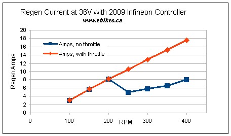
With our controllers shipped before Feb 2010, regen was not enabled by default. To enable regen, it was necessary to open up the controller and then short the pad labelled BK to Ground with a jumper. On controllers shipped before Feb 2010, there were two levels of braking force: maximum regen was achieved by squeezing the ebrakes while engaging the throttle, while a lesser regen current was possible by using the ebrakes only and no throttle. The graph below shows our measurements of the regenerative braking current as a function of the wheel speed, both with and without the throttle applied.
Is Regen really worth it?
In city riding with stop and go conditions, our own first hand experience is that regenerative braking in the somewhat hilly town of Vancouver will increase the range of a battery pack from anywhere between 6 to 14%. If your battery pack can handle this, and you have a direct drive hub motor, then there is very little case not to use regen. If nothing else, it saves substantial wear of your brake pads and provides a nice 'weather independent' means of slowing down. However, regen does cause a reversal in the torque direction on the motor axle, and if the axle nuts are not done up really tight this can result in axle wiggling and loosening up in short order.
What is Auto-Cruise and how is it enabled?
Note: auto-cruise does not work if you have used the two pin connector to reverse the direction of the motor, it also does not seem to work on the most recent 2012 batches of 40A controller units.
The controller auto-cruise is enabled by soldering a small jumper between the controller pad labeled 'CR' and any available ground pad. Once enabled, if you hold the throttle steady at any particular position for a full 6-7 seconds, then you can release the throttle and the controller will maintain the same power. This can be useful for relieving thumb or wrist strain on long ebike trips. However, it can also be disconcerting if you are not aware of it and expect the power to turn off when you let go of the throttle. You can snap out of the cruise mode by either touching the throttle on again or squeezing the ebrake levers if you have those connected. Do note that auto-cruise does not work if you have used the two pin connector to reverse the direction of the motor.
How do I modify the controller for more than 48 Volts?
In our current controller offering, both the 25A and 40A controller models will work with 60 and 72V batteries as-is.
The Infineon controllers sold prior to July 2011 have a somewhat limited design for their 12V linear regulator, which makes it difficult to have the same controller work with both 36V packs and 72V batteries. If you want to run with more than a 48V battery pack, then it was essential to replace the 2 watt power resistor R1 on the PCB with a higher series resistance. For 60V operation required 400 ohms, while 72V operation needed about 600 ohms. There is approximately 50mA of current through this resistor, so we recommend putting two 2W resistors in series to handle the heat.
One other issue is that the controllers were designed to have a fixed 57V regen cutoff voltage. That meant that regen would not work with a higher voltage battery pack unless you tricked the controller into thinking everything is running at a lower voltage. This was achieved by changing the small 0805 surface mount resistor R12, from 2.4kOhm down to about 1.6kOhm. This mod would increase the regen cutoff up to 84V, and it will also raise the low voltage cutoff from 27V to 40V.
What is the wiring pinout to attach it to motor XYZ?
We've made the pinouts of the hall and power leads consistent between any of the motors purchased from us and these controllers, be it eZee, Nine Continent, or Crystalyte. They will just plug together and work, even though the actual colour sequence may not match up. If you have a 3rd party motor, then it will almost certainly have a different connector and pinout standard, and it is up to you to figure out and hook up the correct wiring between the hall signals and the phases. There are in general 36 possible ways to connect a sensored controller to a hub motor (6 pairings for the hall signal leads and 6 pairings for the power leads). Of those, only 3 will work correctly, the rest will either shake the motor or cause it to rotate slowly with a heavy growl.
If you are attaching to a 3rd party motor, you'll find that there are 3 colours for the phase leads and the same 3 colours for the hall signals. Suppose the motor uses orange, purple, and white wires, while our controllers have the more common colours of yellow, green, and blue. As a first guess, you could try:
| Yellow <-> Purple |
| Green <-> Orange |
| Blue <-> White |
Do this exact mapping both for the power leads AND the phase leads. If the motor spins correctly, then great. If not, you then swap any pair in the mapping. So, for instance:
| Yellow <-> Purple |
| Green <-> White |
| Blue <-> Orange |
Where the orange and white were swapped, and then it should spin fine. You could also have swapped the purple and orange, or purple and white, instead. That means that if your motor also uses the yellow, green, and blue colour coding, you should as a first attempt try just matching the colours. If that doesn't work, then swap any arbitrary pair of them, just be sure to swap the same pair both with the hall signals and the power leads. If it happens that your motor uses a different set of colours for the phase leads and the hall signal leads, then you'll have to resort to a lot more trial and error.
As it is now, the infineon controllers have a direct colour matching with the Nine Continent and BMC hubs. However, with both the Crystalyte and eZee motors, a swap is required. With our connector standards it is the blue and the green that are swapped.
Note that the 3 working sequences are all just cyclic permutations of each other. If you take a working sequence, and then rotate all of the phase and hall signals over one, then it will still work:
| If this works |
So would this |
and this |
| Yellow <-> Yellow |
Yellow <-> Blue |
Yellow <-> Green |
| Green <-> Green |
Green <-> Yellow |
Green <-> Blue |
| Blue <-> Blue |
Blue <-> Green |
Blue <-> Yellow |

 Canadian
 Full Length Cable Harness: The controllers come with sufficient length (140cm) of heavy gauge phase and battery wire that they can reach front and rear mounted motors with only one set of connectors near the hub.

 Integrated ON/OFF Toggle Switch: The front plate has an easily accessible on/off rocker switch that lets you turn off the controller and cut all power draw from the battery even when you leave the battery plugged in. This is especially handy with soft case batteries (like Allcell, PING, RC LiPo etc) that lack their own power switch.
 Performance MOSFETs: The 25A and 40A controllers are assembled with authentic IRFB4110 or better mosfets, under 4mOhm guaranteed, while the 20A and 35A devices have devices spec'd to 6mOhm or less. That enables the controller to run with more current and less heat generation than the 10mOhm mosfets typically used.
 Waterproof Gasket: The entry wires are well sealed with a silicone rubber gasket that prevents any water ingress into the controller housing. The controllers can safely be mounted exposed on the bike for maximum airflow and cooling without worry of water damage in the rain.