Hub Motors

This page is quite dated with content from 2007-2009, and is due to be updated. In the meantime, we recommend reading our Why Hub Motors page for more current information on the many benefits of hub motor drives if you are looking for basic info. And if you want technical info, have a watch of the following two video presentations we gave on the topic for the SPEZI bike show:
Understanding Everything about Hub Motor Drive Systems - Spezi 2020 Live Presentation
In this presentation, Justin will be sharing many things from his 15+ years of extensive experience with all kinds of hub motor ebike systems. Topics will include information on estimating actual motor power capabilities, common failure points, optimal motor selection, regenerative braking, gear reduction styles, thermal limitations, bike compatibility, 2WD systems, and maximizing motor efficiency.
This will be a technical discussion for those looking to better understand the capabilities and applications of hub motors in ebike drive systems. It will include slide show images as well as live use of our motor simulator tools.
Deep Dive into Ebike Motor and System Efficiency
This will be another live video presentation from Justin Lemire-Elmore that will focus on everything about motor efficiency and system efficiency as it applies to ebike drives. We'll first explore when you should and shouldn't care about efficiency, and then go into the nitty gritty on choosing the most efficient setups for any given scenario.
This will cover mid-drive setups, both geared and direct drive hub motor setups, and will address a number of "what if" questions. Like: Is it better to go fast on the uphill so that the motor efficiency is higher or climb more slowly so that there is less power required? What is the best gear ratio to be at in a mid-motor?
The content will be be more technical than the last two presentation and will build off the initial talk on basic motor theory, which we recommend watching as a primer (https://www.youtube.com/watch?v=c96n0Ma2rLY )
Direct Drive Hub Motors
Slick and discreet, the hub motor is steadily emerging as the standard drive method for not just ebikes, but scooters, solar cars, and many other light electric vehicles. With a hub motor conversion, there is no need for external mounting brackets and drive chains to support a motor and transmission. Instead all of this is contained inside the wheel which mounts on your bike like any other wheel. There are two basic categories of hub motors: direct drive and geared.
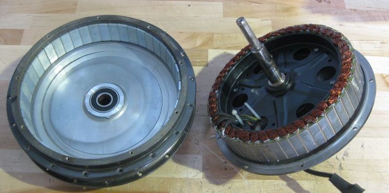
The direct drive hub motor is about as simple as things get. Imagine taking an electric motor, but holding the axle and letting the body of the motor spin. Now lace a bicycle rim onto this spinning motor body and there you have it, no moving parts other than the wheel itself.
Typically these are radial-flux Brushless DC (BLDC) machines that have an array of permanent magnets on the inside surface of the hub. The stator windings are attached to the axle, and the hub is made to rotate by alternating currents through these windings. In a DC hub motor, the magnets are on the axle, and the windings are actually spinning on the inside of the hub. A carbon brush transmits electricity to the spinning windings via a commutator plate.
The one disadvantage of the direct drive scheme is that they are usually large and heavy for their power output. The reason for this is that the wheel speed is quite low, around 200 rpm. The power density available from an electric machine is directly proportional to the speed between the magnets and the winding, so in order to get adequate power and torque output the motor has to be large. In a geared transmission the motor is often spinning over 3000 rpm, and hence a much smaller motor can deliver the same power.
One way to increase the relative speed between the magnets and the windings is to move to a larger diameter motor. You can see this evolution with the BionX hub, which has a radius about 50% larger than the Crystalyte, but is quite light and narrow. However, there are mechanical complications to making the motor too large in diameter while keeping the weight down, so a practical trade-off has to be made.
Common to all direct drive hub motors is that they are always mechanically engaged. This is both a good thing and a bad thing. It is good because it makes regenerative braking possible. All direct drive hub motors can be made to do regen whether they are equipped to do so or not. Both the BionX and TidalForce have sophisticated controllers which allow varied braking energy to be stored back in the battery, while most of the Chinese kits like Crystalyte, Golden Island, and Wilderness Energy need 3rd party controllers to do so. Always engaged is bad because it means that you are always overcoming the rolling resistance of the motor even when you are not using it. Depending on the symmetry and quality of the motor, this additional drag torque can range from imperceptible to feeling like you are always riding with a flat.
Geared Hub Motors

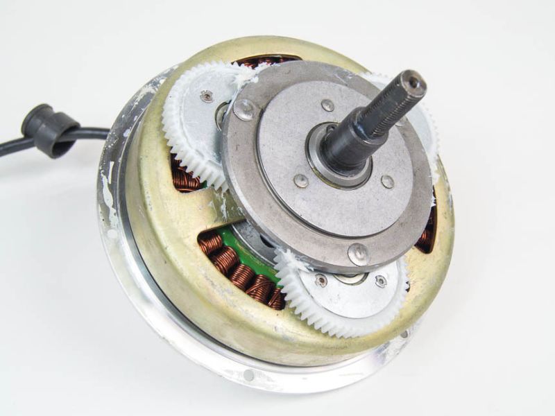
As you can imagine, a geared hub motor has gearing inside it to reduce the high speed of a fast and efficient motor to the low speed of the wheel. From the outside, a geared hub motor is usually smaller in radius but wider than a direct drive hub. On the inside, they can take a variety of different forms although most frequently they have an outrunner motor that drives the center of a planetary gear set linked to the rotor.
The geared hub concept takes the weight advantages of a transmission drive and packages it into the simple looking and easy to install hub motor. These typically weigh about 50% less than an equivalently powerful direct drive machine, and they often have superior torque outputs. The German-made Heinzmann for instance can produce up to 80 Newton-meters (N-m) of torque, compared to about 35 N-m for typical direct drive machines. There are also geared hub motors made by Sanyo, eZee, Ethinkar, and several other Taiwanese companies.
Almost all of the geared hub motors on the market have a freewheel inside. That means there is very little rolling friction to spin the wheel when you are not using the motor, but it eliminates the possibility of regenerative braking.
These advantages of the geared hubs have to be weighed against their downsides. Geared hubs are generally more expensive, there are many moving parts which are prone to wear, and they generate audible noise.
Although it would be possible to have a geared hub motors with multiple speeds, as far as I know every system currently on the market is still just single speed. There are some people who argue passionately that ebikes should have multiple transmission ratios so that the same 500 watt motor can both haul you slowly up a 15 degree hill and zip you along on the flat while always operating around the peak efficiency zone. But if the market is any indicator, the increased costs and complexities from multi-speed drives outweighs their advantages.
Technical Refresher on Permanent Magnet Machines
Hub motors for electric bicycles are almost universally permanent magnet machines, either brushed or brushless. Permanent magnet motors have the highest power density of any common motor type, and they are also the easiest to understand. Both brushed and brushless motors have identical performance characteristics so the discussion below applies equally to both types.
As a thought experiment, imagine hooking up a DC motor to a power supply while holding the shaft locked. As you increase the current from the supply, the torque on the motor shaft would increase as well. The relationship is linear, twice the current yields twice the torque.
Now, disconnect the supply and connect a voltmeter across the motor leads instead. With the motor stationary, you will see zero volts. But start spinning the shaft and you'll read a voltage, directly proportional to the speed that the shaft is spun. This is referred to as the back-emf voltage, and is also expressed by a simple relationship V = k2RPM. If you derive expressions for K1 and K2 from from elementary physics, it is found that they are directly related to each other because they both result from the same flux interactions between the magnets and coils. With the rotational speed is given in RPM, then K1 = K2 * 2Pi/60. If you know how the torque-current relationship, then you also know the voltage-speed relationship and vice versa.
Suppose now the motor is connected to a voltage supply, but the shaft is left to spin freely. Initially, there will be a large current flowing through the motor as given by Ohm's Law. I = V/R where R is the winding resistance in Ohms. This produces a correspondingly large torque (T=K1*I) causing the shaft to accelerate. As the shaft spins faster and faster, the back-emf voltage increases. This reduces the current through the windings because there is less available voltage to push the current, so I = V-emf / R. The motor shaft continues to accelerate until the back emf voltage is nearly equal to the supply voltage. At this point, the current has been reduced close to zero, just enough to produce a torque that overcomes the frictional forces on the motor.
The torque-speed relationship between these two extremes is a simply straight line, given by the equation w = V/k - R*T/k2. Notice that there are only two parameters needed to characterize this 1st order model of a motor, 1) the motor constant K, and 2) the winding resistance R. For a given K, the smaller the resistance R, then the less the speed drops when the motor is loaded, and hence the more powerful the machine. The motor constant K determines both how much voltage is required to make the motor spin at a certain speed, and how much torque it will output for a given current.
If you take the same motor and wind it with twice the number of turns of copper, then k will double, so the motor will require twice the voltage to reach the same speed, but it will only need 1/2 the current to output a particular torque. Notice that the power input (V*I) for a given torque and speed is the same in both cases. The power lost in the copper is the same too, since twice the number of turns means twice the length at half the wire area, so 4 times the resistance. Power loss goes as I2R, so halving the current is exactly canceled by a 4-fold increase in R. The important point here is that rewiring the motor for a different K value does _not_ change the motors fundamental performance in any way, provided that the same total amount of copper is used.
A third property that is important to characterizing a permanent magnet motor is the torque needed to simply turn the shaft. This is often called the cogging or drag torque and results from both the strong forces between the iron poles on the rotor and the magnets, and the induced eddy currents caused by the moving magnetic field. On direct drive hub motors, this torque is quite substantial, between 0.3 to 1 N-m, and it increases with the motor speed. Proper engineering and tight manufacturing tolerances can reduce this torque, but it is always a lot higher in permanent magnet motors with iron poles than any other type of machine.
The amount of power put into a PM motor is equal to the battery voltage times the current. The amount that is converted into mechanical power is equal to the back-emf voltage times the current. The conversion efficiency from electrical to mechanical energy is therefore simply the ratio of the back-emf voltage to the applied voltage.
When the motor is unloaded, it spins up to a point where the back-emf voltage is quite close to the battery voltage, and so the conversion efficiency is almost 100%. However, all of the mechanical energy produced is used to overcome this internal cogging losses, and no power is available as useful torque on the shaft. The efficiency from the perspective of output power to input power is 0%. As the motor is then loaded, the speed goes down so the electro-mechanical conversion efficiency goes down, but a significant percentage of torque produced is now available at the output shaft, so the overall motor efficiency increases. Load the motor further still, and then the losses from the cogging torque become insignificant to the I2R losses in the copper, and the efficiency starts to roll down again.
If you take two motors with the same K and R values, but different cogging torques, then the one with the lower cogging torque will exhibit higher efficiency. But this efficiency peak is only in the low power end of the graph, under heavy loadings the two graphs converge. For a respectable power density, a PM motor should typically be run at about 80% of the unloaded speed, corresponding to roughly 80% efficiency. Whether or not the motor has 95% efficiency at low powers is pretty insignificant in terms of the amount of energy it will draw on an actual trip, so it's generally not about basing motor decision on purported peak efficiency.
Crystalyte Hub Motors in Depth

At the moment, the only hub motors on which we've worked extensively are those from Crystalyte. These motors are of good value. They are manufactured with nowhere near the polish and precision of Heinzmann, for instance, but for 1/5th the price you get reliable performance and an appreciable power output. They offer a large selection of different configurations, and Crystalyte openly publishes the technical specifications of their motors, while most other companies don't let you read past the marketing department.
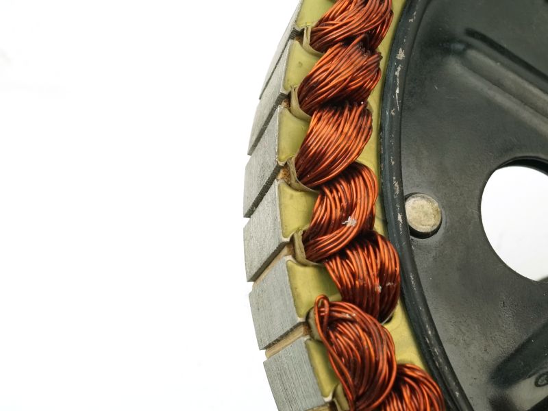
On the Crystalyte website, you'll see a large number of motors listed and characterized like 406, 408, 409, 4011. The last digits refer to the number of turns of copper around each stator pole. So for instance, a 406 has 6 turns, the 4011 has 11 turns.
The torque that is produced by one of these motors varies in direct proportion to the total current flowing around each pole. So in the above case, a 406 motor with 15 amps flowing through the winding has a total of 90 amps around the pole. The 409 motor would need just 10 amps to have 90 amps around the pole and hence the same torque output.
One false and oft-repeated conclusion is that therefore the 409 is a higher torque motor than the 406 because it can produce the same torque with fewer amps, or likewise more torque with the same amps. This is not the case. All 400 series motors can deliver exactly the same torque at exactly the same efficiency. The lower winding count motors just need more current to do this, but because they have fewer turns of a shorter length of heavier gauge wire, they can handle high currents with minimal loss. To use a concrete example, lets compare a 404 with a 408. The 408 has twice the number of turns than the 404, so the copper wire in the windings has 1/2 the cross sectional area and twice the length, for a total of 4 times the winding resistance of the 404. For a given torque output, the 408 needs only 1/2 the amps, but because it has 4 times the resistance the net electrical loss (I2R) is exactly the same.
Another consequence of having a larger number of turns around each stator is that the voltage induced in the winding by the passing magnets is increased in direct proportion to the number of turns. So for instance, at a certain speed of rotation, the 408 motor will produce twice the back-emf voltage as a 404 motor rotating at the same RPM. To power a motor, the battery pack voltage needs to be greater than the back-emf voltage, and so the 408 motor needs twice the voltage to spin at the same speed as a 404. However, it will only draw 1/2 the current, and you can see that the net power input (Volts * Amps) remains the same.


 Canadian