
 Canadian
Brompton Kit


Brompton's are among the most exquisite of compact folding bicycles, but also among the more challenging to convert cleanly into electric assist. The front fork uses tiny 8mm dropout slots and a narrow 75mm hub width, the rear tire folds into the bottom bracket eliminating most mid-drive options, and the triple fold adds challenges to the cable routing and component location. But once properly outfitted, they make excellent electric bikes. Portable, compact, easy to travel with, and a delight to ride.
We’re happy to offer purpose built conversion kit packages tailored for this bike for the discerning enthusiast, with 2 motor sizes and a range of control options. Please note of course that Brompton does not endorse any 3rd party modifications to their bike and will be quick to point out that electrifying your Brompton bike will void your Brompton warranty, as is their right. Of course it is your right to do what you like with a product that you purchased and own, and we're here to help you have fun with that.
Motor Choice
At the moment, we have two hub motor options for the Brompton forks: a small 1.8kg geared SOFP motor, and the larger Crystalyte SAW20 direct drive motor.

| SOFP | SAW20 | |
| Weight | 1.8kg | 3.2kg |
| Diameter | 144 mm | 184 mm |
| Motor KV | 13.4 RPM/V | 13.6 RPM/V |
| Phase Resistance | 0.182 Ohm | 0.24 Ohm |
The geared motor is recommended when you want the most discrete package, when weight is a top priority, or when you want a motor that freewheels with zero drag when pedaling without assistance. It offers decent power levels (upwards of 500 watts) and can climb hills pretty well, but being a geared motor it also some audible buzz and it can't do regenerative braking. *The SOFP motor option is discontinued as of 2023.*
The Crystalyte SAW20 motor is ideal when you want the fastest and most powerful setup and aren't quite as concerned about motor weight. Being a direct drive motor it is totally silent when running and can also do regen braking, which is a great feature on bikes like the Brompton that only have rim brakes available. It's also more ammenable to running at high system voltages with Statorade cooling, as we demonstrated here.
Full performance under different load conditions is available from our motor simulator, by choosing the Clyte SAW2013 or Brompton SOFP options from the drop-down list, and creating a 16.7" custom wheel size.
Display Options

You also have the option to choose whether you want a comprehensive V3 Cycle Analyst device or a simple 5-LED display console.
The eZee LED console gives a basic indication of your remaining battery charge, and the up/down arrows let you set 5 different power levels. It is a great option for an introductory throttle controlled ebike setup where a simple non-technical display is all that is needed.
The V3 Cycle Analyst has a much more complete technical readout of your speed, battery voltage, amp-hours used etc. With the V3 Cycle Analyst, you can not only tune your throttle behaviour, you can also configure the bike for automatic pedalec assist modes with a PAS or Torque sensor so that you don’t need to press a throttle for power.
Pedalec Modes

If you opt for a V3 Cycle Analyst display, then you have the option to add pedalec control of the Brompton without needing to use the throttle for power. Both the simple PAS sensor and the more elaborate torque sensors can reduce thumb fatigue while riding and lead to a pleasant automatic assistance.
The 12 Magnet PAS sensor installs on the left crank and simply senses when you are pedaling. You then configure the Cycle Analyst to put out a baseline power whenever you pedal, and use the throttle for when you want to override that with manual control.
The torque sensor takes this up a notch by sensing not just cadence, but also the force that you are applying to the pedals. This allows the Cycle Analyst to regulate the motor power in proportion to your pedal effort. As you ride harder, you get more assist. However, the installation of the torque sensors is considerably more involved than the split disk PAS sensor, involving a replacement of your bottom bracket and (in the case of the ERider device) your crank arms. We only recommend this option to those with greater familiarity with bike mechanics.
Other Accessories
There are a few useful accessories that aren't part of the kit bundle on the store site but which can be worth adding separately to the order.

- Headlight: Both the eZee LED meter and the Cycle Analyst include a DC power plug bringing out your battery voltage to run a front light with no extra wiring. The Cycle Lumenator casts the brightest beam while the potted Electrolights can mount cleanly under the Cycle Analyst with a long bolt through the enclosure.
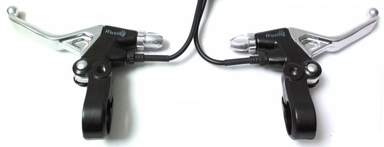
- Ebrake Cutoffs: We don't recommend to bother installing ebrake cutoffs with small geared motors, but on the direct drive SAW20 motor this is a great With the 20A Grinfineon and Baserunner controllers you can add any of the ebrake cutoff levers to the order if you want to have regenerative braking whenever you squeeze the brakes. We don’t include brake levers in the kit because for most people it’s easiest just to keep the original levers fitted on the bike, but if you want them they are available here.
Installation Guide
Installing the Front Hub Motor
The Brompton kits operate with a front hub motor that replaces your ordinary non-electric wheel.

- Start off by removing the original wheel from your fork. Loosen the axle nuts, deflate the tire, and if you don't have a spare 16" tire you can remove the original tire and inner tube and move these to the hub motor wheel instead.

- Remove the nut and washers from the axle and set them aside.
- Slide the motor wheel into the fork dropouts, with the wire exiting on the left side. Pay attenion to the axle's anti-rotation key on the non-wire side: this protrusion should point downwards in order for the axle to seat properly all the way up to the top of the dropouts.

- Slide the torque arm plate over the axle, seeing that the bent tab on the top locks into the hole in the fork. This tab secures the axle against the torques that are present when the motor is running. The metal plate should be a snug fit over the axle, so don't be concerned if it feels tight to slide into place and you can tap it on if necessary.
- On the right side, follow the torque plate with both the washer and nut, being sure to firmly tighten the axle nut to 15-20 Nm.

- On the left side, you will also be sandwiching the wire hoop for the nylon hook between the torque plate and washer, as depicted.
- Notice that the wire exits facing upwards in this image; that is a consequence of the axle key orientation in some early versions of the SAW20 motors. In general the wire will point downwards. There will be a sticker on the hub motor with an arrow pointing in the direction of rotation. In general the cable will exit on the left side in current kits with the molded HiGo connectors, but earlier kits with the Anderson plugs may have the cable on the right.
SOFP motor

The SOFP motor is a small light weight motor that has been configured for the Brompton fork. It is important to note that the wire will be on the right side of the bicycle, and is routed differently. Furthermore, the SOFP motors have axles that require special hardware.

The wire exit side of the motor sits on the drive side of the bicycle. From the fork, the order of hardware is: 3mm Torque arm, thick washer, nylock silver nut.

On the left side, the short axle must use thinner hardware to acommodate the wire hook for folding. From the fork, the order of hardware is: 2mm Torque arm, wire hook, thin washer, thin nylock yellow nut.
Installing Motor Controller
After much experimentation we found that the most ideal location for the motor controller on the Grin Brompton kit was just above the fender on the front wheel. This keeps the wire cable lengths to a very minimum, it leaves the on/off switch easily accessible, and it stays protected and out of the way once folded. To facilitate this mounting location, we manufacture a bent aluminum bracket that secures to the front brake mount and provides mounting holes for the controller flanges.

- Remove nut from Brompton front brake assembly, but do not remove the bolt.
- Important Also remove the cupped washer from directly under the fender bracket, as the thickness of this washer is the same as the mounting plate. Is this washer is not removed, then there may be insufficient threads remaining on the bolt for the nyloc nut to fully engage.
- Slide the controller bracket on the back of the fork and fender bracket, and secure it in place with the nut.
- Be sure to hold the bracket level while tightening the nut so that it does not pivot. There should be at least 1 full thread protruding past the end of the nut so that you can be sure that the nyloc nut will not be able to rattle loose, which could cause the controller bracket and front brake assembly to come off the bike.

- Use the three M5 button cap screws to screw the controller to the mounting plate through the controller flanges, with the cables facing forwards towards the fork.
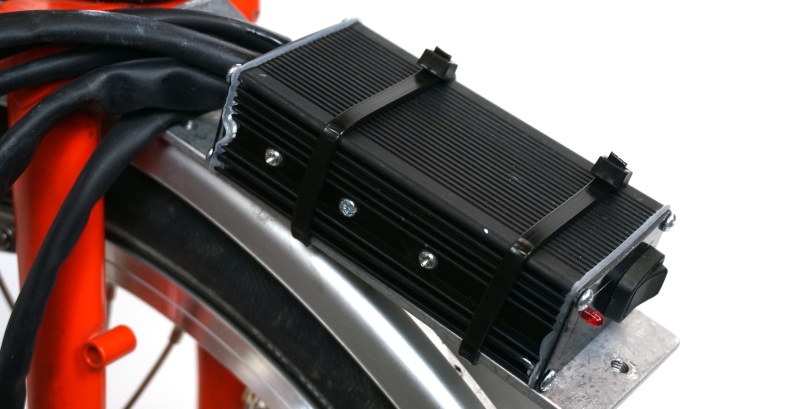
- In the case of the 15A controller which does not have screw flanges, use a pair of cable ties to hold it in place.
Setting Up the Handlebars
The handlebars on the Brompton bike don't provide as much real estate for throttles, lights, and other accessories, but they can still fit the essentials OK.

- Remove the hand grips from the bar. Modern grips will have a screw and come off easily, while older grips can be difficult to remove without the assistance of compressed air or lubrication.

- Loosen the screw that holds each brake lever onto the handlebars. This allows the brake lever angle to be shifted to accommodate the new hardware.

- Slide the thumb throttle on the right side of the bar, followed by the 3-prong plastic spacer which prevents the rotating throttle from binding against the grip.

- If you have a V3 Cycle Analyst, then similarly install the 3 position switch on the left bar.
- If desired, trim down the length of the grip so as to account for the width that the new hardware now occupies on the bar.

- Orient the throttle such that it is comfortable to press with your thumb and does not interfere with the motion of your brake lever.
- Slide the grips back into position and ensure that the throttle mechanism springs back properly without any binding.

- Remember to tighten down the brake levers when finished adjustments.
Installing the Cycle Analyst or LED Console
The Cycle Analyst includes a special stainless steel mounting bracket that holds it secure and centered on the Brompton handlebars.

- Remove the M7 handlebar bolt from the stem.
- Replace this with the 30mm long M7 bolt included with your kit. This will provide the extra threads to which the Cycle Analyst will attach.
- Tighten the M7 Bolt to at least 15 Nm so that the handlebars are secure again.

- Insert the Cycle Analyst bracket over the protruding threads, and hold the bracket in place with the included M7 Nyloc Nut.
- You may need to move the shifter up slightly to get the Cycle Analyst into place.

- If you have the LED console instead, then install that by sliding the extrusion pieces apart and fit it over the handlebar on the left side of the stem, so that it clears the shifter.
(Optional) Installing the PAS or Torque Sensor
The Pedal Assist sensors are optional upgrades to the Grin Brompton kit to provide pedalec operation. The split disk PAS sensor is straightforward to install:

- Remove the metal retention ring from the magnet disk and separate the two halves.
- Close the disk back together over the exposed spindle of your crank. The image shows it on the left crank, but if there is insufficient exposed spindle here then you can install in on the right side instead. Pay attention to the orientation of the disk: one side says "Working Surface" and this side must face inwards, towards the sensor.

- Use cable ties to secure the PAS pickup sensor to the diagonal bracing tube from the bottom bracket, with a ~5mm spacer block to move it closer to the disk.
- Adjust the PAS sensor pickup to be centered on the magnets with 2-3 mm of lateral clearance.

If instead you are using the ERider torque sensor, then you will need to remove your cranks and bottom bracket and move the chainring over from the original crankset to the 5 bolt spider supplied with the torque sensor. .
Cable Routing
Few things will spoil the look of an ebike conversion more than a tangled mess of wires and connectors all over the place. And with a folding bike like the Brompton, messy cables can get caught and snag during the fold and unfold process, so please follow the routing suggestions here. We’ve ensured that the cable lengths in the kit are about optimal to reach the hardware without any excess slack to deal with.
Layout Strategy:
- Run your throttle, handlebar switch, (and possible ebrake cutoffs) along the left and right brake cable housing. If you have a Cycle Analyst, these wires will then part from the brake cables at the stem and bend upwards to connect with the CA’s accessory plugs.
- If you don't have a Cycle Analyst, then run your throttle wire along the front brake cable right down to the fork, and then have it curve upwards to the controller's 3-pin throttle plug.
- Run the Cycle Analyst or LED console cable down along the stem, then follow the front brake housing right down to the front fork and connect it to the 6-pin CA plug on the controller.
- Wrap the motor cable up around the left fork blade and mate both the 3 anderson plugs and the 5-pin hall plug to the motor controller.
- If you have a PAS sensor or Torque sensor, then run the cable along the rear brake housing up to the 5-pin plug on the Cycle Analyst. Use cable ties if necessary to hold the wire snug to the frame around the seat stem so that it doesn’t get pinched by the rear wheel folding in.
Once you have all your wires plugged in and following the layout path, the next step is to bundle everything together:

- Use the included Spiral Wrap to secure all electrical wires to the nearest brake housing. This will make 3 or 4 parallel wires look and operate like a single cable, and effectively hide the electrical wires from sight.

- If you have wires going back to the rear of the bike, be sure to leave 10cm of extra space without spiral wrap on either side of the cable hoop on the frame. The rear cables here must be able to slide freely left and right as the rear wheel folds in, otherwise the folding process will be hindered.

- Use a Velcro sleeve to cover all the accessory connectors under the Cycle Analyst. This will provide a clean cover for the connections but one that is still easy to open and access.

- Similarly, use a Velcro sleeve to hold the motor connectors and controller plugs together against the rear of the left fork blade. Motor connectors on the side of the fork blade can impede with the folded bike, preventing the handlebar from hinging all the way down.
- Finally, the controller battery cable is expected to loop up into the front bag where the battery is typically stored. However, it is long enough to reach a battery on the rear rack of you prefer it there.
The completed bike should look barely busier than the original Brompton pre-electrification, and should fold down in a without cables getting in the way.
