
 Canadian
Cycle Analyst V3
The V3 Cycle Analyst is the next step for the CA product line to not only monitor what is going on in an ebike, but also control it. In the V2 CA we included basic throttle over-ride capabilities for speed, current, and low voltage limiting that proved quite popular, but fundamentally it was mostly a passive display. With the V3 Cycle Analyst, all the ebike signals, from your brake cutoffs to your throttle to your pedal sensor, are first intercepted at the Cycle Analyst. The CA then processes all of these inputs to determine how to control your bike, which it then does via one standard throttle output signal to the controller.
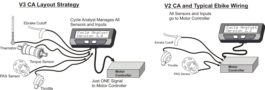
There are many advantages to this arrangement. In the traditional setup, any features that you wanted on the ebike, be it cruise control, torque sensing pedalec modes, temperature rollback etc. had to be supported by your particular motor controller. An OEM ebike company can design a custom controller that works with a specific set of input sensors, but DIY projects don’t have this luxury. With the V3 Cycle Analyst, you have access to all these advanced sensor and control schemes no matter what model motor controller powers your system.
Here are some of the more popular features you can include by using the V3 CA as your central ebike/EV console:
|
|
Plus many advanced capabilities to discover, and of course all the functionality that you have in the V2 CA like volts, speed, amps, amp-hours, %regen, watt-hours/km etc.
User Manuals
 Here is the manual for the current V3.1 Cycle Analyst device and firmware which explains the majority of settings and configurations that users would run into. For those with a technical background looking for a deep dive then much of the CA3's hardware and earlier 3.0X firmware is exceedingly well documented in the unofficial users guide written by Endless-Sphere forum member Teklektik. Of particular interest would be sections 6 (tips and tricks) and the appendices, which go over how to hook up a V3 Cycle Analyst to controllers that don't have a CA plug, how to log trip data with a smartphone, how to tune the PID speed control feedback loops, and numerous other topics.
One instruction often overlooked by new users is the importance of resetting the Cycle Analyst each time you start off with a fresh charge in the battery. This is done by pressing and holding the right button until the RESET message shows up.

Once the trip has been reset, the amp-hour accumulator and trip distance both return to zero. This enables you to see how many amp-hours have been consumed from the pack over the course of your trip(s) so that you have a very good idea of how much charge is remaining. It also ensures that the battery cycle counter is accurate and gives you more immediate wh/km trip statistics.
The two most common accessories for the V3 Cycle Analyst are the Auxilliary Input controls and PAS/Torque sensors, and information on the selection and setup of those devices is in the just linked pages rather than here.
Display Screens
The V3.1 Cycle Analyst has a total of 12 display screens to scroll through, and as a user you can mask screens that you don’t want to show up from the preferences section of the setup menu.
Display #1 – Main Screen
The primary display screen shows at a glance all of the key info you would want to see from the bike. There is a battery fuel gauge in the top left, plus a readout of your pack voltage, speed, and battery power draw. The button right corner toggles between showing your accumulated trip distance and accumulated battery amp-hours, and if a temperature sensor is enabled it will show the temperature too.
Meanwhile, on the bottom left there are two additional graphic blocks. A throttle slider icon shows visually where your input throttle is at, switching to a flashing mode if throttle auto-cruise is latched, and then to a brake lever if ebrakes are engaged. Adjacent to this is a human power indicator that works if you have a PAS sensor enabled, indicating either your human power or your pedal cadence.
Also note that if you exceed the speed limit, then the speed units will flash, and if you hit the battery low voltage cutoff then the voltage sign will flash. If you are below the minimum start speed, then the speed number itself will flash.
Display #2 – Electrical Only
 The 2nd screen only shows electrical stats; Volts, Watts, Amps, and Amp-Hours. It is useful when using the CA on non-vehicle systems where all the additional details on the first screen are not relevant.
Display #3 – Human Power
 The 3rd screen is interesting for people who have a torque sensor in their system. The top line shows key vehicle stats: your voltage, amps, and speed, while the 2nd line displays your human power input and pedal cadence.
Display #4 – Energy Mileage
 The next display is the same popular readout from the V2 CA devices which shows the net watt-hours taken from the battery pack, as well as your energy ‘mileage’ in units of Wh/km or Wh/mi. This is the EV equivalent to gas mileage in L/100km, and the smaller the number the better energy economy and longer range you’ll get from a battery pack.
Display #5 – Human Stats
 Screen number 5 is a summary of the human power statistics for the trip, showing the total human watt-hours, along with the average watts and average pedal cadence. Note that the human watts are only averaged while the rider is pedaling, so if you coast or ride throttle only for a while this won’t reduce your average.
Display #6 – Regenerative Braking
 The relative benefits of regen are debated at length in the ebike community, and the point of this screen is to at least help provide analytic numbers to the discussion. On the left you will see the % by which your range has increased as a result of regen, and on the right it toggles between the total forwards and reverse amp-hours that were accumulated. (The Ah display on the 1st and 3rd screen is the net difference).
Display #7 – Max and Mins
 The next stat shows the electrical max and mins on the system. Usually the max amps isn’t all that interesting since it will be the same as your controller current limit, but the Amin will show the max regen current, and the multiplication of Amax and Vmin will typically coincide with the maximum power draw as well.
Display #8 – Speed Stats
 This one is self explanatory. Max speed, average speed, and trip time. In some cases you may see a somewhat wild value for MaxS, this can be the result of a double bounce in the speedometer pickup switch and adjusting the relative magnet and sensor positions can solve it.
Display #9 – Temperature Stats
 This screen is new in the CA3.1 firmware and allows you to see the current, average, and peak temperatures if the CA has a temperature sensor configured. Note that the average and peak temperature statistics are not preserved if the CA is turned off and on.
Display #10 – Odometer
 Here you can see the same total trip distance as the first screen but with much greater precision, along with the lifetime odometer for the vehicle.
Display #11 – Battery Stats
 The battery statistics includes the lifetime cycles and watt-hours of the battery pack, along with a current estimate on the battery’s internal resistance in Ohms. The Cycles count increments every time you reset the CA by holding the right button, and both the Cycles and Total kWhrs are unique to each battery. So if you have both an ‘A’ and ‘B’ battery enabled, you can keep separate stats on each pack.
The battery resistance is computed on the fly by seeing how much voltage sag accompanies changes in current draw. This stat is useful, not only to quantify the performance of a pack but also to assess its aging and cold weather behavior. The internal resistance of most batteries will start to increase well before there is much noticeable decrease in the amp-hour capacity.
Display #12 – Diagnostics
The final display screen is most useful when initially setting up the CA for various feedback and control modes. On the top line you can see both the input throttle voltage from the user, as well as the output voltage that the CA is sending to the motor controller.

The bottom line has a row of limit flags showing which throttle limiting feedback loops are currently engaged. So if you are exceeding the speed limit, the ‘s’ becomes a large ‘S’, and similar flags for the current limit (a/A), power limit (w/W), low voltage rollback (v/V), and thermal rollback (t/T). If for instance you have the bike setup for proportional pedalec assist, then the commanded power limit of the CA is being set by your pedal effort, and so the power limit flag ‘W’ will be set showing that the CA is in a power limit control loop.
CA3.1 Setup Menu
The setup menu is accessed by pressing and holding the left button for several seconds, or by holding the right button down while the CA is powered up. It is a 2-level deep menu list organized into 17 high level groups to let you adjust over 60 different settings. Remember the left and right buttons toggle left and right (or up and down), while pressing and holding the right button selects something.

There are also a few visual cues to help with the navigation. Arrows on the left and right show when there are more items in the current menu level, while a straight bar indicates you are at the end of the list, and pressing the next button will take you up a level. As well, for each of the 18 categories there is a small preview line showing some of the key settings and real-time input signals that affect these settings (eg your throttle voltage, PAS sensor state, ebrake signal, torque sensor voltage etc.) Click the + beside each section to read the details for all menu items.
Speedometer Setup Menu
 The Cycle Analyst reads the vehicle speed by timing pulses that come into the speed sensor input line. For direct drive motors or geared motors with internal speed sensors, there will normally be many pulses per wheel revolution, while CA3-DPS devices with an external spoke magnet and sensor typically have just one pulse. When the wheel is rotated, you will see the small arrow beside the 'P' symbol point downwards every time the magnet is in front of the sensor.
The CA displays vehicle speed whenever there are pulses coming into the Spd input from either a motor hall signal (CA-DP device) or a spoke magnet and sensor (CA-DPS device). Wheel size and poles settings must be correct for an accurate speed display.
[ Spd->Units ]
Select to use units of kilometers or miles. Changing this setting will not rescale existing distance-related values such as odometer, speed limits etc.
[ Spd->Circumf ]
Exact wheel circumference in mm. The table below shows typical values for common tire sizes. A more accurate value can had by placing a dot of paint on the tire, riding forward one or more tire rotations, and measuring the distance on the road between dots.
| Tire Size | Circumf (mm) | Tire Size | Circumf (mm) | Tire Size | Circumf (mm) |
|---|---|---|---|---|---|
| 16 x 1.50 | 1185 | 24 x 2.125 | 1965 | 26 x 2.25 | 2115 |
| 16 x 1-3/8 | 1282 | 26 x 1-1/8 | 1970 | 26 x 2.35 | 2131 |
| 20 x 1.75 | 1515 | 26 x 1-3/8 | 2068 | 700c x 23 | 2097 |
| 20 x 1-3/8 | 1615 | 26 x1-1/2 | 2100 | 700c x 28 | 2136 |
| 24 x 1-1/4 | 1905 | 26 x 1.5 | 1995 | 700c x 32 | 2155 |
| 24 x 1.75 | 1890 | 26 x 1.75 | 2035 | 700c x 38 | 2180 |
| 24 x 2.00 | 1925 | 26 x 2.0 | 2075 | 700c x 2.0 | 2273 |
[ Spd->#Poles ]
The number of pulses on the Spd input that is considered one full wheel revolution. For direct drive (DD) hub motors using a CA-DP device, pole count is the number of magnet pole pairs in the hub (usually between 8 to 26). Geared motors with an internal speed sensor typically have 6 pulses per revolution and can also use a CA-DP device.
Mid-drive motors or geared motors without an internal speed sensor require a CA-DPS device with external speed sensor. The pole count is the number of magnets on the wheel (usually 1). Additional wheel magnets can be added for better low speed control.
The table below gives values for common DD motors. The number of poles can be determined by rotating the wheel slowly one complete revolution. The pole count is the number of times the arrow next to 'P' on the SETUP SPDOMETER screen flips DOWN then UP.
| Motor Family | # Poles |
|---|---|
| Crystalyte 400, Wilderness Energy | 8 |
| Crystalyte 5300, 5400 | 12 |
| TDCM IGH | 16 |
| Crysatlyte NSM, SAW | 20 |
| Crystalyte H, Crown, Nine Continent, MXUS, and most generic 205mm DD motors |
23 |
| Magic Pie 3 and other 273mm DD Motors, plus the Nine Continent 212mm motors | 26 |
Battery Setup Menu
 The Cycle Analyst device needs to know certain details of your battery pack in order to show an accurate state-of-charge indicator and to protect the battery against over discharge. The preview line in the setup menu shows the nominal voltage and chemistry currently configured, and indicates if you have just one or two battery presets active..
Battery settings must be correct for the State Of Charge (SOC) icon on the main display screen to accurately reflect the battery charge level. This information is configured in terms of the battery chemistry and number of series cells rather than a nominal voltage. For instance, a 36V lithium battery is 10 series cells of Li-ion chemistry, while a 36V lead acid is 18 series cells of SLA chemistry.
[ Batt->Volts Disp ]
Chooser to select whether the main CA screen displays just the battery pack voltage or alternates between pack voltage and average cell voltage. The average cell voltage is not measured but is computed as (pack voltage)/(number of cells).
[ Batt->Batteries? ]
Chooser to select one battery (A) or two batteries (A & B)
-
Batt A only: Only one battery pack is configured
-
Batts A&B: Allows selection between two different battery packs. Battery statistics are maintained separately for each and the selected battery can be changed at any point by tapping the left console button while the right button is held down.
[ Batt->A or B ]
Chooser to select the battery pack presently installed (A or B).
[ Batt->Chemistry ]*
Chooser to select the cell chemistry of the present battery pack:
-
Li-ion: Lithium Ion, which includes various chemistries such as Li Manganese, Li Cobalt, etc. This option encompasses almost all the common 18650 style rechargeable lithium batteries. They have a somewhat steady drop from 4.2V down to 3.6V and then a more rapid fall off to 3.0V.
-
LiPo: Lithium Polymer, a standard ebike grade cell used in many lightweight lower-end lithium ebike battery packs. This has an almost linear voltage drop from 4.2V to 3.0 V / cell.
-
RCLiP: high 'C' discharge rate Lithium Polymer batteries used in R/C vehicles and similar. These chemistries have less voltage drop during discharge, going flat at about 3.5V rather than the 3.0V of most ebike LiPo.
-
LiFe:Lithium Iron Phosphate, used in PING and A123 packs. These cells have a lower voltage than other types of lithium. They fully charge to 3.6V / cell and remain constant between 3.3 to 3.2V / cell over most of the discharge.
-
SLA: Sealed Lead Acid, the properties are more or less the same for other types of lead acid pack. Full charge at about 2.25V/cell and going totally flat around 1.9V.
-
NiMH: Nickel Metal Hydride; use this option for Nickel Cadmium (NiCad) as well. These cells have a nominal voltage of 1.2V. They were common in ebikes during the 2000's but have since been almost entirely replaced with lithium.
[ Batt->String# ]*
This is the number of cells connected in series to make the battery pack which defines the nominal battery voltage. This setting is essential for the battery SOC icon to correctly show the charge level. The table below shows the series cell count for common nominal battery voltages.
| Chemistry | 24V Nominal | 36V Nominal | 48V Nominal | 52V Nominal | 72V Nominal |
|---|---|---|---|---|---|
| Li-ion, LiPo | 7 | 10 | 13 | 14 | 20 |
| LiFe | 8 | 12 | 15/16 | 16 | 24 |
| SLA | 12 | 18 | 24 | - | 36 |
| NiMH | 20 | 30 | 40 | - | 60 |
[ Batt->Capacity ]*
Capacity of the battery pack in amp-hours. This setting is used to improve the accuracy of the battery fuel gauge display while drawing current. For lithium and nickel chemistries, the nominal advertised Ah is generally correct. With SLA, you should take the Peukert effect into account, and scale the rated Ah down by 30-35%. For instance, a 12Ah SLA has a useful capacity closer to 8Ah.
[ Batt->Vlt Cutoff ]*
Low voltage rollback. When the CA detects the battery voltage falling below VltCutoff, it will gradually scale back the power draw to prevent the voltage from dropping lower. This protects lead acid batteries from sulfation, nickel batteries from cell reversals, and with BMS protected lithium batteries it can keep the battery above the BMS trip point to prevent the battery from abruptly shutting down.
Cutoff voltage per cell varies by chemistry and application; 2.9 to 3.2 V/cell is typical for lithium ion batteries although many users set a higher cutoff to limit how far they drain their pack. The table below shows VltCutoff range for common nominal pack voltages, and applies equally well to lithium, lead, and nickel batteries.
| Nominal Pack Voltage |
Suggested VltCutoff |
|---|---|
| 24V | 19-21V |
| 36V | 30-32V |
| 48V | 39-42V |
| 52V | 42-45V |
| 72V | 60-64V |
Please note that the VltCutoff is not a substitute for a BMS circuit on DIY lithium packs, as the CA does not have awareness of individual cell voltages and cannot detect cell balance issues or shorts.
[ Batt->LoVGain ]
The feedback gain setting for the low voltage rollback. A higher number results in the power scaling back more abruptly when voltage falls below the VltCutoff.
Throttle Input Setup Menu
 This section configures how the Cycle Analyst responds to the input throttle signal of your ebike. The preview line provides a live readout of the currently measured voltage on the pin, as well as an indication of how this is scaled into either a pass-thru voltage, or a current or a watts limit. A typical hall effect ebike throttle will sit at about 0.9V when off and increase to ~4.1V when twisted all the way. When not thottle is plugged in the voltage sits at 0.0V
These settings refer to the operator throttle plugged into the black 3-pin connector of the Cycle Analyst. They determine how the throttle input signal is scaled over a min to max voltage range to obtain a 0-100% throttle interpretation over the entire operator throttle rotation. The default values (min 1.0V, max 4.0V) are broadly suitable for hall effect throttles, though you can tweak them to vary the deadbands at either end or to accommodate potentiometer and other throttle types.
[ ThrI->Cntrl Mode ]*
Chooser determining how the user throttle affects controller operation
-
Pass-Thru: User throttle is linearly mapped from the input throttle range to the output throttle range, with throttle rate limiting applied if necessary. Throttle behavior is similar to having the throttle directly connected to the motor controller. [Default]
-
Current (A): User throttle controls the battery current from zero up to the value in MaxCurrent. This mode provides for better modulation of motor power over the entire speed range. When using this mode, MaxCurrent should be set equal to or lower than the controller current limit.
-
Speed (kph): User throttle directly controls the speed of the bike from 0 to the value in MaxSpeed. This mode can be useful for special projects but is not a recommended for most ebike scenarios as small throttle motions can result in large pulses of power as the bike attempts to track the changes.
-
Power (W): User throttle controls the power to the motor controller from 0 to the value in MaxPower. The effect is very similar to Current Throttle mode, but provides a response that is insensitive to battery voltage sag. When using this mode MaxPower should be set equal to or lower than the battery voltage times the controller current limit.
-
Disabled (ZERO): This mode ignores the input throttle and sets the output throttle signal low. The output can then only go high if you have one of the PAS modes enabled and are pedaling. You can achieve the same thing by simply unplugging the operator throttle, but this option can be useful if you want swap between different presets with and without active throttle modes.
-
Disabled (WOT): This mode ignores the input throttle and sets the output throttle signal to MaxThrottle unless one of the limits is exceeded. This mode provides legacy support when using a V3 CA on an old controller designed for the original CA V2 connector standard. Controllers with this old standard can only limit an external throttle signal from the CA plug, they cannot use the CA plug as the primary throttle input.
IMPORTANT: Do not select this mode if the CA V3 output is connected to a CA3 compatible controller since the CA will immediately apply full throttle on power-up causing the bike to run away. -
Bypass: This mode is the equivalent of connecting the throttle directly to the controller to completely eliminate the CA from motor/controller behavior. This differs from PassThru mode in that ThrIN is sent directly to ThrOUT with no processing whatsoever: no min/max range adjustments, no ramping, no limiting, and no autocruise or PAS support.
IMPORTANT: This is only a diagnostic mode and is not intended for normal ebike use. All normal CA protections are inoperative (e.g. low voltage, max current).
[ ThrI->Zero Thrsh ]
Voltage threshold for the lower bound of the input throttle (ZERO throttle). The throttle is considered OFF when the input throttle signal is less than this setting. The threshold should be set at least 0.1V higher than the actual input throttle voltage when the throttle is OFF. If set too close to the actual minimum voltage signal, electrical noise can make it appear that the throttle is briefly open and so cause the CA to disengage autocruise or briefly disable PAS output resulting in momentary power loss.
To optimize this setting, zero the throttle, examine the voltage shown on the 'SETUP THROT IN' screen, and add at least 0.1V.
[ ThrI->Full Thrsh ]
Voltage threshold for the upper bound of the input throttle (FULL throttle). The throttle is considered at FULL when the input throttle signal is greater than this setting. The threshold should be set at least 0.1V lower than the maximum input throttle voltage to ensure 100% throttle is available even if there is voltage drift.
To optimize this setting, open the throttle fully, examine the voltage shown on the 'SETUP THROT IN' screen, and subtract at least 0.1V.
[ ThrI->FaultThrsh ]
Sets the throttle input voltage fault detection threshold. If the throttle signal input is higher than FaultThrsh the CA will assume there is a throttle fault and immediately reduce the output throttle signal to MinOut. This type of input fault is typical if there is a break or disconnection of the throttle ground wire while the 5V and Signal are still attached. This setting should be at least 0.15V higher than the maximum operator throttle voltage. If it is too close, there may be erroneous throttle fault errors from electrical noise and drift. The default is 4.35V.
[ ThrI->Auto Cruis ]*
Autocruise is a form of cruise control that automatically maintains a fixed throttle level. Holding the throttle steady for the configured time causes the throttle slider on the main screen to flash indicating that autocruise is engaged and the throttle can be released. That throttle level is maintained until autocruise is disengaged by braking or re-applying the throttle.
- Off: Auto Cruise Mode is Disabled
- 2 Sec: Auto Cruise will engage after 2 seconds
- 3 Sec: Auto Cruise will engage after 3 seconds
- 4 Sec: Auto Cruise will engage after 4 seconds
- 5 Sec: Auto Cruise will engage after 5 seconds
- 6 Sec: Auto Cruise will engage after 6 seconds
- 8 Sec: Auto Cruise will engage after 8 seconds
IMPORTANT: Normal autocruise behavior maintains power after the throttle is released which can be alarming if unexpected. Ensure all riders are thoroughly acquainted with autocuise operation before enabling this feature.
[ ThrI->Cruise Hld ]
Sets the throttle voltage range for auto cruise to consider the throttle 'stationary'. Small numbers are more sensitive and can make engaging autocruise difficult. Large values reduce motion sensitivity but can cause unintended autocruise engagement.
Throttle Output Setup Menu
 The CA3 sends its own output throttle signal to control the motor controller. The preview line shows the range of this output throttle from min to max, whether it is is a voltage signal typically used for ebike motor controllers, or a pulse based signal common in RC speed controllers .
The Cycle Analyst sends the Throttle OUT signal (ThO) to the motor controller via the CA-DP connector. It can be set up as either a variable voltage signal for ebike controllers or as a digital 1-2mS pulse for RC controllers. The min to max output range should be adjusted to correspond to the throttle input range of the controller to ensure the controller is driven to max at full operator throttle and is completely OFF when the operator throttle is closed.
Ramping options can help achieve smooth power engagement and remove the aggressive edge from powerful motor systems. When Up, Down, Fast, or PAS rate limiting are in effect a small {U,D,F,P} flag appears before the OUT voltage on the Diagnostic Screen to assist in tuning these settings.
[ ThrO->Outpt Mode ]
Selects between a steady analog voltage output on the CA Throttle Output line or a 1-2ms RC servo style pulse output. Almost all ebike and EV controllers operate off a voltage throttle signal, while the R/C pulse mode enables the CA to control compact ESCs from the hobby industry.
[ ThrO->Min Out ]
This is the voltage or pulse width sent to the controller for ZERO rider throttle. It should be about 0.2V below the actual voltage where the motor controller starts to respond. The default value of 1.0V is fine for most setups, but if the controller does not start turning the motor until 1.4 or 1.5V from the CA, then the Min Out setting could be increased to ~1.2-1.3V for a faster throttle response with less deadband.
[ ThrO-> Max Out ]
This is the voltage or pulse width sent to the controller for FULL rider throttle. Most ebike controllers will achieve full output between 3.5 to 3.9V on the throttle, and the CA3's Max Out should be at least 0.1V higher than this to achieve full power.
NOTE: Many controllers have a throttle overvoltage fault similar to ThrI->FaultThrsh. The CA3's Max Out must be lower than this controller fault or the controller will shut off at full throttle.
[ ThrO->Down Rate ]
Determines the maximum rate at which the throttle output can ramp downwards. For safety reasons you would generally leave this at a high value so that the system can shut off promptly, but there can be times where a slower disengagement of motor power is preferred. Values of 4 to 8 V/sec are recommended. Ebrakes cut power immediately and are unaffected by this setting.
[ ThrO->Up Rate ]*
Determines the maximum rate at which the throttle output can ramp upwards once current greater than FastThrsh is detected. This setting is popular for smoothing out the harsh kick on powerful systems. A lower value in V/sec will result in a longer time for the throttle to ramp up and results in a more gentle application of power. Values of 0.5 to 3 V/sec are recommended.
[ ThrO->PAS Rate ]
Determines the maximum rate at which the throttle output can ramp upwards when engaging in PAS mode. This can be used to achieve a smooth PAS power application while still allowing for a fast response with the throttle. Operation is otherwise as with UpRate.
[ ThrO->Fast Rate ]
Determines the maximum rate at which the throttle output can ramp upwards when controller current is less than FastThrsh. When current reaches FastThrsh, the rate becomes governed by UpRate or PASRate. This dual rate approach allows the Throttle output to quickly reach a level that starts having a measurable effect on the motor before then dropping to the normal Up or PAS rate limit. This eliminates time lag for a ramped throttle output to catch up with the bike when you apply the throttle and are already moving. Values of 3-8 V/sec are recommended for controllers that have an immediate response. For controllers with built-in ramping (such as eZee), or sensorless controllers that have a startup routine delay, a lower FastRate rate may be required to prevent overshoot.
[ ThrO->Fast Thrsh ]
Determines the threshold controller current at which the CA's output ramp switches from FastRate to UpRate or PASRate. This setting should be quite low for direct drive hub motors, such as 1-2A. However, for gear motors or mid-drives, the setting should be a bit higher than the no-load current required to accelerate the motor from stopped, typically 2 to 4 Amps. A value of 0A disables FastRate so only UpRate or PASRate is applied.
Speed Limit Setup Menu
 There are both minimum and maximum speed limit settings available, and the 2nd line preview shows the speed limit set point present in the current preset. If you don't want to use the Cycle Analyst to limit the vehicle speed in any capacity, then this can be left at the default setting of 199 kph.
The CA can be configured with a speed limit to cut motor power when the bike exceeds that limit. This speed limit is implemented as a PID controller and so there are three gain terms that may need to be tweaked to achieve the desired responsiveness when the bike hits the limit point. Surging or oscillation at the speed limit setpoint or power cutouts on hard acceleration (powerful bikes) are indications that speed gain adjustments are needed.
[ SLim->Max Speed ]*
Upper speed limit. The CA rolls back throttle output voltage whenever speed exceeds this setting.
OEM->AbsMaxSpeed determines the maximum value for this setting.
[ SLim->Strt Speed ]*
The minimum starting speed that must be reached before the CA will allow power application. This is useful for RC drives or systems with sensorless controllers that do not work well from a dead start. The rider must pedal the bike up to StrtSpeed before power is applied.
[ SLim->MxNoPdlSpd ]*
The maximum speed at which the throttle will apply power without pedaling in any PAS mode. This feature supports European pedalec legislation which requires pedaling the bike for motor power, but which provides exemption below a certain speed (e.g. 6kph) in which case use of a throttle without pedaling is permitted. Applies only if a PAS device is installed.
[ SLim->Regen Lmtg ]
Chooser to select if Speed Limiting should use regenerative braking to help control the maximum speed.
-
Disabled: Speed is limited exclusively by reducing power. Above the speed limit the motor power is reduced to zero, but regenerative braking is not applied allowing the rider to continue to coast or pedal above this speed limit. [Default]
-
Enabled: Regenerative braking is used to enforce the speed limit setpoint. This means that regen may engage automatically when descending hills even without the rider applying the ebrakes. Proportional throttle regen (EBk->PropRegen) need not be enabled. This feature requires a controller with 0.0 - 0.8V throttle regen function (e.g. Grinfineon or Phaserunner).
[ SLim->IntSGain ]
Integral (I) feedback gain for the speed PID control loop. Lower values give smoother control and less likelihood of hunting, but can increase the time it takes for the speed limit to stabilize. This adjusts the correction for accumulated 'past' speed error.
[ SLim->PSGain ]
Proportional (P) feedback term for the speed PID control loop and displayed in terms of Volts / (mph or kph). If set to 0.5V/kph, the throttle output will immediately drop by 0.5V for each km/hr the bike exceeds the set speed limit. This adjusts the correction for the 'present' speed error.
[ SLim->DSGain ]
Differential (D) feedback term for the speed PID control loop. This is used to dampen speed oscillations by determining the ability of the CA to scale back power in anticipation of breaching the speed limit due to acceleration towards that limit. Values in the 100-300 range seem to work well, but lower values are often required for vehicles capable of hard acceleration. This adjusts the correction for 'future' anticipated speed errors.
Power and Current Limit Setup Menu
 Both these limits have a similar effect, though amp limits are usually used to keep a battery's discharge current level within a BMS or cell specification, while watt limits are usually used for keeping power levels into the motor within the motor range. If these values are higher than the native limits of the motor controller, then the controller limits will come into play first.
These settings configure power and current limits for the ebike. The Cycle Analyst cannot increase the natural limit of the system, so setting the CA current limit to 40A will have no effect if you have a 20A motor controller. However, you could use it to limit current to only 15A to avoid over-taxing a small battery that is not rated to deliver full 20A discharges. Both the Amp and Watt limits have associated feedback gains that may need to be tweaked for a quick response without oscillation or surging.
[ PLim->Max Current ]*
Sets the CA current limit in Amps, commonly used to reduce stress on the battery pack or limit the available system power. This value may be further scaled down by one or more of the throttle, the Analog/Digital Aux inputs, or temperature limits. This setting can be left at the default high value if no CA current limiting is desired, but if either thermal rollback or aux / throttle amp adjustments are active, then MaxCurrent should be set equal to the controller battery current limit. OEM->AbsMaxAmps determines the maximum value for this setting.
[ PLim->Max Power ]*
Sets the CA power limit in watts. It has very similar effect as a current limit, except that the resulting power does does not change with variations in battery voltage. This is typically set to no more than the battery voltage times the smaller of the controller current limit or the continuous current rating of the battery. This setting determines the 100% power setting for Power Throttle or Aux Input power scaling. If neither of those features are used, this setting can be left at the maximum value. OEM->AbsMaxPower determines the maximum value for this setting.
[ PLim->AGain ]
Feedback gain for the current control loop. This affects the current limiting response and can have a noticeable effect on throttle behavior when operating in Current Throttle mode. If this setting needs adjustment, increase it until current limiting begins to be rough or oscillating and then reduce the setting by about 30%.
[ PLim->WGain ]
Feedback gain for the power control loop. This affects the CA's response in any power limit mode, which includes Power Throttle and most of the PAS modes, even if the normal Max Power limit is not in play.
If this setting is too high, the system may be prone to surging and oscillation while maintaining constant power, while too low of a value can result in a sluggish response. Typical values for well behaved WGain are 8-25.
Pedal Sensor Device Setup Menu
 The hardware configuration of both basic Cadence PAS sensors and torque sensors is done in the PAS Device setup menu. Here the preview lines shows critical information about the state of the pedal sensor. The P and D arrows show the live state of the pedal sensor input signals, and one or both of these should toggle as the pedals are rotated for the CA3 to detect the rider's pedal cadence. This preview also shows a live voltage reading of the torque signal. Most torque sensors sit at either 1.5 or 2.5V with no force on the cranks and then increase or decrease in voltage as pedal force is applied. Understanding this behavior is critical to checking that a torque sensor is wired up and configured properly.
These settings tell the Cycle Analyst the physical characteristics of the installed pedal assist device. The CA needs to know the number of pulses per crank revolution and the forward/reverse pedal sense. If there is a torque sensor, it must also know how the torque signal is scaled into meaningful units of Newton-meters. These are one-time settings made at installation time; tuning the way the PAS device operates is achieved by the PAS Configuration Settings in the next section.
[ PASD->Sensr Type ]
Chooser to select the type of PAS sensor installed.
-
Disabled: There is no PAS device installed. This deactivates all PAS functionality and makes SLim->MxNoPdlSpd inoperative.
-
Basic PAS: The sensor is a simple cadence sensor, which provides pulses when the cranks are pedaled. Both 1 wire (only pulses with fwd pedaling) and 2 wire (quadrature signals) are supported.
-
Row Bike: The sensor is a simple cadence wheel for a rowing bike, with signals to distinguish forward and reverse motion. Rather than computing the RPM based on rotation speed, the CA instead displays the strokes per minute based on how often there is a direction reversal of the cadence wheel.
-
Custm TRQ: The sensor is either a custom device type with unique settings or one of the preconfigured types below.
- Thun BB:
- TDCM BB:
- NCTE BB:
- Sempu BB:
- ERider BB:
- CyclStokr:
These are sensors for known device types. These selections cause preconfigured defaults to be copied into place for other settings in this category. The sensor type remains as selected if those other defaults remain unmodified, however, changing a default setting will change this sensor type to 'Custm TRQ'. Downloading one of these preconfigured sensor types from the Setup Utility will similarly set other settings to the associated preconfigured defaults exactly as if the preconfigured type had just been selected by CA Console Setup, overriding the other settings that may have been present in the Setup Utility.
Note: The Sempu BB is manufactured with two different interface styles. The version selectable here has the '2-wire' interface distributed by Grin. Units from other vendors may require subsequently customizing PASD->SignlType to '1-wire' in CA Console Setup. The ERider sensor was originally supplied with an 18 pole speed signal, and was updated in 2021 to 36 poles.
[ PASD->PAS Poles ]
Number of pulses generated in one full rotation of the pedal sensor. This is equal to the number of magnets on simple magnetic ring cadence wheels. For internal sensors it can be measured by counting the number of times the P arrow on the SETUP PAS DEVICE preview screen flips up and down during one pedal rotation. This setting is populated automatically when a known sensor type is selected, and must be set correctly for accurate display of human pedal RPM.
[ PASD->Signl Type ]
Both Basic PAS and Torque sensors generate a cadence signal pulse as the cranks are rotated. The signal may pulse only on forward pedal rotation with just a single wire, or it may also indicate direction of rotation which requires two wires.
This setting determines the number of input wires that carry cadence pulses so the CA can best use the available information. The type can be determined by examining the arrows next to the 'PD' on the SETUP PAS DEVICE preview screen as the crank is slowly turned. On a single wire sensor only the P arrow will changes, while on a 2 wire sensor both the P and D arrows will flip UP/DOWN.
-
1 Wire: Cadence pulses appear on the RPM input with no simultaneous change to the DIR input.
-
2 Wire: Quadrature encoded cadence pulses appear on both RPM and DIR inputs.
[ PASD->Dir Plrty ]
Controls whether 5V on the Dir pin is considered forward or reverse pedaling. If the Dir pin is not connected, then it should be set to 5V = Fwd. Trial and error tests may be required to find the proper FWD or REV setting if the device is quadrature encoded. This setting is populated automatically when a known sensor type is selected.
[ PASD->Trq Scale ]
Sets the scaling factor for converting torque sensor output voltage to newton meters. For devices that sense torque on only one side of the crank, the value should be doubled to simulate the net left and right pedal torques. The value can be set either positive or negative and is populated automatically when a known sensor type is selected. For TDCM Sensors, additional tuning is required and may be initially guesstimated as the number of teeth on the front chainring. So a 44T chainring would be about 44 Nm/V. This option is present only for torque sensor types.
[ PASD->Zero Torq ]
The configured zero-torque offset voltage and the present live torque voltage are displayed. The right button should be pressed with the pedals unloaded (zero torque) which configures a new zero-torque voltage from the present live torque voltage. This voltage is displayed when the button is released. Note that magnetostrictive torque sensors (like THUN and NCTE) don't return to the same zero point very well after high torque excursions. This option is present only for torque sensor types.
Pedal Sensor Configuration Setup Menu
") This setup menu configures exactly how the CA3 responds to the signals from the pedal sensors in order to regulate motor power when you are riding in PAS mode. It is possible to have a torque sensing bottom bracket device attached to show human watts and RPM, but still choose to not have a PAS control and run exclusively under throttle command. The preview line indicates which form of pedal sense control (if any) is active in the current preset, and gives a snapshot of the max assist level.
This setup menu configures exactly how the CA3 responds to the signals from the pedal sensors in order to regulate motor power when you are riding in PAS mode. It is possible to have a torque sensing bottom bracket device attached to show human watts and RPM, but still choose to not have a PAS control and run exclusively under throttle command. The preview line indicates which form of pedal sense control (if any) is active in the current preset, and gives a snapshot of the max assist level.
These settings configure how the ebike system responds to pedal action when a PAS device is installed. PAS devices can be adjusted for a wide range of performance and these settings are used to tune the PAS system to your personal taste for both basic pedal cadence sensing as well as more advanced torque sensing devices. The use of an Auxiliary Input device is recommended to increase or decrease the assist level on the fly while riding.
[ PAS->PAS Mode ]*
Chooser to select the pedal assist type. In all cases, assist is enabled only when the throttle is off, and is immediately overridden by throttle control if throttle is applied.
Basic (Pwr), and Torque modes use the Power PID controller to achieve constant power control to the motor. In these modes PLim->WGain may need adjustment to reduce assist oscillation or smooth power application.
-
No Assist: No assist is provided of any kind. However, because a PAS device is installed, the SLim->MxNoPdlSpd setting has effect even in No Assist mode. This can be useful for simple sensor wheels in locales where regulation imposes a pedaling requirement to enable throttle operation, but where PAS assist is not desired. [Default]
-
Basic (Pwr): When pedaling is detected with no applied throttle, the motor delivers a constant power assistance equal to the power configured by StrtLevel. This power level can be further modified to increase or decrease with pedal cadence according to the ScaleFctr setting.
-
Basic (ThO): When pedaling is detected with no applied throttle, ThrOUT is set to 0-100% as configured by StrtLevel, and can be further scaled by ScaleFctrto increase or decrease with pedal RPM.
This mode can be used instead of Basic (Pwr) mode with conventional controllers to have PAS level set the approximate cruising speed of the bike rather than the motor power. It can also be used to have cadence based control of motor torque with torque throttle controllers such as the Phaserunner.
-
Torque: In this PAS mode, the motor power scales in proportion to the human power as measured by the torque sensor. The StrtLevel term sets the minimum pedal power required to start the electric assist, and the ScaleFctr sets how much each additional watt of human power is then multiplied by the motor.
[ PAS->Strt Level ]*
The meaning of this setting depends on the PAS mode.
-
Basic (Pwr) Sets the baseline power assist delivered when pedaling without the throttle. If there is a ScaleFctr term to further vary the assist with cadence, then this is the power output up to 50 rpm. It can be nice to set StrtLevel to a comfortable background assist and then use the throttle whenever full power is needed.
-
Basic (ThO) Sets the baseline ThrOUT percentage delivered when pedaling without the throttle. If there is a ScaleFctr term to vary the the assist with cadence, then this is the throttle percentage up to 50 rpm. For most ebike controllers, this sets an effective percentage of the maximum vehicle speed under pedal assist. For torque throttle controllers, it allows PAS mode to control the motor torque output.
-
TorqPAS: Sets the threshold human power before proportional torque assist begins to be applied. For instance, if set to 100 watts then there will be no assist when pedaling lightly but proportional assist will begin when rider effort exceeds 100W. This value can be set negative, which has the effect of providing motor assist when turning the cranks even with no effort; additional proportion power increases from this baseline with additional effort.
[ PAS->Scale Factr ]*
The meaning of this setting depends on the PAS mode.
-
Basic (Pwr): Sets how much the PAS power level varies with pedal cadence above 50rpm. Values between 5-20 W/RPM can provide a boost when downshifting and reduce the need for the rider to use PAS Aux Input adjustments for their desired power. Negative values can be used for single speed bikes to provide more power at low speeds and less as the rider speeds up. A setting of 0 has means that the output power is constant regardless of changes to pedal cadence.
Basic (ThO): Sets how much the throttle output percentage varies with pedal cadence above 50rpm. Recommended for ebikes running a Phaserunner or other torque throttle controller to achieve increased motor torque when downshifting.
-
TorqPAS: Sets the proportional assistance multiplier that is provided based on your human power pedal input. For instance, a setting of 2.00 W/HW means the electrical motor watts will be double the applied human watts.
[ PAS->Asst Avg ]
Determines the amount of pedal rotation (in terms of the number of pulses) over which the torque signal is averaged. The human pedal torque undulates with each turn of the cranks so the signal must be averaged to prevent corresponding pulses of motor torque. Higher values yield smoother power assist at the cost of slower response to changes in pedal effort.
This should be a multiple PASPoles with sensors like the THUN which only measure torque on one side. It can be set in multiples of half pedal rotations for torque sensors that measure both left and right pedal force (eg TDCM). This setting is populated automatically when a known sensor type is selected.
[ PAS->Strt Thrsh ]
Sets the threshold minimum time between pedal sensing events to cause the CA to assume that the rider is 'pedaling' and activate motor assist. If set to a long period, assist will begin sooner when starting from a standstill, but there will also be a longer delay before the motor cuts out if pedaling stops within a single revolution.
Sensors with more poles give brisker response because the CA gets sensor pulses more quickly, and can use shorter threshold times.
[ PAS->Stop Thrsh ]
After the first complete crank revolution, sets the minimum time that must be maintained between pedal sensing events for the CA to assume that the rider is still pedaling. If the time between pedal events is longer than this threshold, the CA will assume that pedaling has stopped and will cease power assist. Short values result in a more immediate cutout in power, while longer values allow for pedal assist even at slow pedal speeds. Sensible values are usually between ' 0.5x-1.0x the StrtThrsh.
Temperature Setup Menu
") The CA can optionally monitor a temperature signal via the 2-pin plug and automatically scale back motor power as temperature crosses a threshold and heads towards the MaxTemp setpoint. When temperature limiting is in effect a special icon appears on the main screen that shows the relative temperature in the ThrshTemp to MaxTemp range. Power is limited proportionately 0-100% via the MaxCurrentlimit over this range. The preview line in the setup menu shows the current voltage on the temperature pin and how that is scaled into degrees. With no sensor attached the voltage will hover near 5V. A 10K NTC thermistor will register around 3.3V at room temperature.
The CA can optionally monitor a temperature signal via the 2-pin plug and automatically scale back motor power as temperature crosses a threshold and heads towards the MaxTemp setpoint. When temperature limiting is in effect a special icon appears on the main screen that shows the relative temperature in the ThrshTemp to MaxTemp range. Power is limited proportionately 0-100% via the MaxCurrentlimit over this range. The preview line in the setup menu shows the current voltage on the temperature pin and how that is scaled into degrees. With no sensor attached the voltage will hover near 5V. A 10K NTC thermistor will register around 3.3V at room temperature.
The CA can optionally monitor a temperature signal via the 2-pin plug and automatically scale back motor power as temperature crosses a threshold and heads towards the MaxTemp setpoint. When temperature limiting is in effect a special icon appears on the main screen that shows the relative temperature in the ThrshTemp to MaxTemp range. Power is limited proportionately 0-100% via the MaxCurrent limit over this range.
[ Temp->Sensor ]
Chooser to select the type of installed temperature sensor.
-
Disabled: Voltage on the NTC pin is ignored. [Default]
-
10K Thrmstr: (NTC b=3900 in 3.15FW) The input voltage is scaled into degrees Celsius assuming a 10K NTC thermistor with a beta constant of ~3900 (Used in all the motors with L10 connectors from Grin).
-
NTC b=3450: The input voltage is scaled into degrees Celsius assuming a 10K NTC thermistor with a beta constant of ~3450 (Used in the SX1/SX2 Shengyi motors from Grin).
-
NTC Bafang: The input voltage is scaled into degrees Celsius assuming a 10K NTC thermistor with a beta constant of ~3450 and an independent 10K pull up resistor to 5V (Used by Bafang motors with combined temperature/speed signal).
-
Linear Type: The input voltage is scaled linearly into a temperature reading based on a custom scale and offset assuming a PTC (positive temperature coefficient) or silicon device.
[ Temp->0degC Volts ]
The sensor voltage at zero degrees. Only present if Linear Type is selected.
[ Temp->T Scale ]
The scaling factor in units of Deg/V for converting the sensor voltage into degrees. Only present if Linear Type is selected.
[ Temp->Thrsh Temp ]
The temperature at which thermal CA current limiting begins to be applied (i.e. 0% limiting).
[ Temp->Max Temp ]
The temperature at which the thermal rollback will have brought the CA current to 0 amps (i.e. 100% limiting). The current limit is scaled linearly from MaxCurrent to zero amps as the temperature increases from ThrshTemp to MaxTemp.
Analog Aux Input Setup Menu
 The 3 pin auxiliary control input on the CA3 supports both analog and digital input modes, and this menu controls how it responds to analog signals which can range from 0-5V (if no digital aux is plugged in) or 0.8-5V (if a digi aux input is also attached). The analog mode can be either a potentiometer or a fixed 2 or 3 position switch which changes voltage based on switch. On the preview line you see a live readout of the voltage on the aux input pin and how this scales a limit if aux limiting is selected. If a Digi Aux input is plugged in as well, then you should also see 0V when the up button is pressed, and ~0.4V when the down button is pressed.
The analog auxiliary input connects via the white 3-pin connector and allows you to use a variable voltage from a potentiometer or a switch/resistor assembly to vary one of the limit settings on the fly while riding.
[ AuxA->Ctrl Type ]
Chooser to select the type of installed analog control.
-
Pot: A 2k-10k potentiometer. This setting can also be used for DIY circuits that present varying voltages to the AuxPOT input.
-
2-Pos Sw: A 2 position switch that is configured to present a low and high signal voltage.
-
3-pos Sw: A 3 position switch that presents 3 different voltage levels to the Aux input. The standard Grin 3-position CA switch uses resistors to provide 1.6V, 2.5V, and 3.3V for switch positions 1, 2, and 3 respectively.
[ AuxA->Function ]
Chooser to select the controlling effect of the Analog Aux control. Choices are identical to those of the Aux Digital function selections but are mutually exclusive so a selection made in one will be excluded from appearing as an available option in the other.
-
Off: The installed control remains configured but is deactivated. [Default]
-
Presets: The control selects the current preset. This option is displayed only if a 2-pos or 3-pos switch is installed; the associated preset count is automatically adjusted to match. This mode overrides the console button 'hot swap' capability as well as Prst->PowerOn.
-
Amps Lim: The Aux control applies a scaling factor to the configured MaxCurrent setting.
-
Speed Lim: The Aux control applies a scaling factor to the configured MaxSpeed setting.
-
Power Lim: The Aux control applies a scaling factor to the configured MaxPower setting.
-
ThrO Lim: The Aux control applies a scaling factor to the configured ThrO-> MaxOut voltage. With most controllers this has the effect of limiting speed by a means that is easier to tune but less precise than true speed limiting.
-
PAS Level: The Aux control scales the final applied pedal assist level. This is one of the most common uses for the Aux Input devices. If there is a cadence dependent term to the PAS output, the scaling applies to the final output including the RPM component.
[ AuxA->Lo Deadband ]
This option is present only for pots configured for a limiting function (non-Preset).
Specifies the voltage offset above the baseline voltage at which the pot will be considered to be at MINIMUM setting. This setting typically ranges from 0.1V to less than a volt and can be tuned to set the point where the potentiometer crosses 0%
[ AuxA->Med Sw Level ]
This option is present only for 3 position switches configured for a limiting function (non-Preset).
Specifies the percentage of the configured maximum limiting parameter (MaxCurrent, MaxPower, MaxSpeed) for the MEDIUM switch setting for 3 position switches. The HIGH setting is assumed to be 100%.
[ AuxA->Hi Deadband ]
This option is present only for potentiometer devices.
Specifies the voltage offset below 5V at which the pot will be considered to be at MAXIMUM setting. This setting typically ranges from 0V to less than a volt and can be tuned to reduce deadband. A proper setting shows a full rotation value of 99% that decreases shortly after the pot begins to be turned downward.
[ AuxA->Lo Sw Level ]
This setting is preset only for switches configured for a limiting function (non-Preset).
Specifies the percentage of the configured maximum limiting parameter (MaxCurrent, MaxPower, MaxSpeed) for the LOW switch setting for 2 or 3 position switches. The HIGH setting is assumed to be 100%.
Digital Aux Input Setup Menu
 The digital aux input mode was added as a new feature to the CA3.1 firmware releases which provides a convenient pair of up/down buttons that can be used to adjust any of the limit settings or the pedal assist level. With the digitial aux input, you can set how many steps you have from min to max value, and set the lower limit to be higher than 0% if desired. The preview line shows how many steps have been selected and gives a snapshot of the current digi aux limit value.
The digital auxiliary input connects via the white 3-pin connector and uses UP and DOWN buttons that are momentarily pressed to increase or decrease the configured setting. Digital Aux controls provide a second connector for an optional analog aux control so that two different settings can be adjusted while riding.
[ AuxD->Ctrl Type ]
Chooser to select the type of installed digital control. The voltages expected by the CA for analog Aux controls are strongly affected by the presence of an installed digital Aux control. It is important to configure the installed digital type even if the function is configured as 'Off'.
-
None: No digital control is installed. [Default]
-
1-Btn: A one button control is installed. Such controls increase levels on every button push and reset to the lowest level on a push when in the highest level. A long push resets to level 0.
-
2-Btn: A two button control is installed. Such controls increase levels on every UP button push until the highest level is reached and decrease levels on every DOWN button push until the lowest level is reached. A long push on either button sets the level to the highest or lowest level respectively.
[ AuxD->Function ]
Chooser to select the controlling effect of the digital control. Choices here are identical to those of the Aux Analog function selections but are mutually exclusive so a selection made in one will be excluded from appearing as an option in the other. This option is not present if no AuxD device is installed.
-
Off: The installed control remains configured but is deactivated. [Default]
-
Presets: The control selects the current preset. The console button 'hot swap' capability is unaffected and operates normally.
-
Amps Lim: The Digital Aux control applies a scaling factor to further reduce the MaxCurrent limit.
-
Speed Lim: The Digital Aux control applies a scaling factor to further reduce the MaxSpeed limit.
-
Power Lim: The Digital Aux control applies a scaling factor to further reduce the MaxPower limit.
-
ThrO Lim: The Aux control applies a scaling factor to the configured MaxOut voltage. This has the effect of limiting speed by a means that is easier to tune than true speed limiting.
-
PAS Level: The Aux control scales the final applied pedal assist level. This is one of the most common uses for the Aux Input.
[ AuxD->Power On ]
Chooser to select the present level when the CA is powered up. This option is not present if no AuxD device is installed or the function is 'Off'.
-
Last level: The CA will boot up with the same level that was active when it was powered down.
-
Level #1: The CA will always default to the lowest level when it boots up.
[ AuxD->Max Levels ]
Configures the number of levels from 1-32. Scaling is [ Min Prcnt ]-100% with equally spaced steps. For example, for steps of 0%, 10%, 20%, select 11 steps (10 steps + 0%) with MinPrcnt=0. This option is not present if no AuxD device is installed or the function is 'Off'.
[ AuxD->Min Prcent ]
Configures the percentage scaling of the lowest level (#1). For example, for three power levels of 40% 70% 100%, select MaxLevels=3 and MinPrcent=40%. This option is not present if no AuxD device is installed or the function is 'Off'.
Ebrake Input Setup Menu
 The CA3 had an input plug for a digital brake cutoff sensor which can be be used to drive the throttle output signal in a 0-0.8V signal range to activate regenerative braking on suitable motor controllers, or a simple cutoff effect on generic motor controllers. The preview line shows the current state of the brake lever and should go from an open lever to a pressed lever when the brake switch is active.
The ebrake connects to the CA via the 4-pin plug and operates as a simple switch. It can operate with both normally open and normally closed switch logic, and can activate regenerative braking with controllers that do regen with a 0.0 - 0.8V throttle signals.
[ EBk->Signal Lvl ]
Chooser to select if a High or Low voltage on the EBk pin signals that brakes are applied. Almost all commercial ebrake sensors use Active Low signaling, but homemade sensors are often easier to design with Active High logic. Select so that the ebrake icon on the preview screen reflects the proper 'released/applied' ebrake condition.
[ EBk->Prop Regen ]
Chooser to select if proportional regen is active when ebrakes are applied.
-
Disabled: Throttle OUT voltage is set to Brake Out when ebrakes are applied. [Default]
-
Enabled: Throttle OUT voltage is set to Brake Out when ebrakes are applied and the rider throttle is ZERO. As the rider throttle is increased with ebrakes applied, the Throttle OUT voltage decreases from Brake Out to 0V to increase the proportional regen braking effect. All Grin controllers support this feature.
[ EBk->Brake Out ]
The CA Throttle OUT voltage when ebrakes are applied. This value must be less than
ThrO->MinOut [Default = 0]. Some controllers recognize values between 0V and ThrO->MinOut as a command to apply regen braking. For Grin controllers, regen braking increases from minimum to maximum in the range 0.8V - 0.0V respectively. Setting BrakeOut in this range selects the baseline regen brake intensity when ebrakes are applied, with values closer to 0V having more braking force and values closer to 0.8V having less braking force.
[ EBk->Min Time ]
This is the minimum time in seconds from the time of application that ebrakes are applied. This fixed minimum time will be extended if the ebrakes continue to be held ON. This feature facilitates mid-drive shifting by briefly removing motor power for a fixed period when tapping the brakes or using a gear shift sensor.
Calibration Setup Menu
 The Calibration setup menu includes settings for the current sensing shunt resistor, the current sensor offset, and the voltage scaling. When the CA3 is used in a direct-plug in application to a motor controller, it's quite important that the RShunt value is set to match what is written on the controller label. If you see a small positive or negative power even when the motor is not running, then the zero amps offset routine in the calibration menu will set the new zero point an will eliminate this small offset.
These settings allow the CA to accurately measure current and voltage. Most are calibrated at the factory on a per-device basis, but the RShunt setting depends on the particular installation and must be set to exactly match the controller or external shunt being used. This is the only calibration setting that you would normally change.
[ Cal->Range ]
Chooser to select the shunt and current range. The Low range mode is appropriate for ebikes while the High range mode is intended for motorcycles and larger EVs. This affects the allowable shunt range and determines if power is displayed as W or kW.
-
Lo (W): This mode is intended for systems with shunt sense resistors that are in the 1-9mOhm range. Current measurement resolution is 0.01A and power is shown in watts.
-
Hi (kW): The high range mode is intended for high current systems that have shunts which are in the 0.1-0.9 mOhm range. All power units are shown in kW instead of W and the current measurement resolution is 0.1A. In addition, all current and power feedback calculations are also affected by the chosen range mode, so that an AGain setting of 50 in low range mode would be equivalent to 500 in the high range.
[ Cal->RShunt ]
This setting calibrates CA current measurement. The CA is only as accurate as the calibration value for the current sense shunt resistor. Most controllers with direct plug-in CA connectors have resistances in the 1.5-6 mOhm range and the Stand Alone CA shunts are 1.00 mOhm. Specifications of high current shunts used in larger EV's are not typically rated by shunt resistance but instead indicate the current draw that causes a 50mV drop. For example, a 200A 50mV shunt has a resistance of 50mV/200A = 0.25mOhm.
[ Cal->Zero Amps ]
This setting calibrates the CA zero current measurement and should be adjusted if the resting current shown in the CA screen is something other than 0.0 amps or watts. The live voltages on the Lo and Hi gain current amplifiers are displayed in real time and should be approximately 2.5V. Pressing the right button sets the 'Zero Amps' offset from the present live amperage measurement. After releasing the button the new Lo and Hi voltage offsets are displayed.
[ Cal->VScale ]
This setting calibrates CA voltage measurement. The factory calibration is about 31V/V using the CA internal voltage divider. If an external divider is employed, then VScale must be adjusted to match the voltage scaling ratio.
Mode Presets Setup Menu
 Mode Presets allow the Cycle Analyst to have up to 3 different preconfigured settings for your power limits, speed limits, and PAS modes, providing for quick and easy switching between economy, off-road, or PAS based modes. Each preset can be given its own name, and switching between presets is easily achieved either via an Aux Input device or by holding the left button and tapping the right button. The preview line shows how many presets are current enabled and which preset is active.
Presets allow you to have two or three different collections of Cycle Analyst limit settings and change between them either with a double console button press or with an Aux Input device. Many settings are global and always in play and so are not controlled by presets.
[ Prst->Crnt Prset ]
Selects which of the possible presets is currently active. This screen is displayed only if either two or three mode presets are enabled.
[ Prst->Preset Cnt ]
Chooser to select the number of available presets.
-
Only 1: Only a single preset is available. The console preset 'Hot Swap' cannot change presets. [Default]
-
1&2 En: Allows selection of one of two distinct sets of CA limit, PAS, and throttle settings.
-
1,2&3: Allows selection of one of three distinct CA limit, PAS, and throttle settings.
[ Prst->Preset Name ]*
Chooser to select one of several fixed names for each preset. The name does not automatically preload any settings, you must create a set of settings that suits the given name.
[ Prst->Power On ]
Chooser to select the active preset when the CA is powered up.
-
Last Preset: The CA will boot up with the same preset that was active when it was powered down.
-
Preset #1: The CA will boot up with preset #1.
[ Prst->Import #1 ]
All per-preset tings from preset #1 are copied into the present preset. This is an optional display that will not appear if the active preset is #1.
[ Prst->Import #2 ]
All per-preset settings from preset #2 are copied into the present preset even if #2 is not selectable. This allows a preset to be defined as a 'default' to initialize other lower numbered presets but not be selectable for modification. This is an optional display that will not appear if the active preset is #2.
[ Prst->Import #3 ]
All per-preset settings from preset #3 are copied into the present preset even if #3 is not selectable. This allows a preset to be defined as a 'default' to initialize other lower numbered presets but not be selectable for modification. This is an optional display that will not appear if the active preset is #3.
Display Customization Setup Menu
 There are a number of display customizations that are possible in order to configure the screens to show the information that is most important to you. This includes selecting up to 13 different items in the custom view field on the main screen (where Ah and Distance are normally shown), the ability to hide any screens you don't care to see both while moving and while stopped, and the ability to automatically return to the main dispaly after a certain time. The preview line shows the first 4 custom view items that have been selected for the main screen.
These settings customize miscellaneous aspects of CA displays from selecting the contents of Main Screen display fields to adjusting the smoothing time for real time screen updates.
[ Disp->Main Disp ]
Chooser to select 'Amps' or 'Watts' for display on the lower left of the Main Status screen.
[ Disp->AuxChg Dsp ]
Chooser to select the main screen display mode when making AuxA or AuxD limiting adjustments. The new limit value can be shown either with the transient pop-up 'Aux Change' screen or more discretely in the top right corner the custom field. This option affects only the main screen - the pop-up always appears for other display screens.
[ Disp->Auto Main ]
Chooser to enable/disable automatic display of the Main Screen after a fixed period of Console Button inactivity. This feature allows the console to be advanced to other screens without the need to manually return to the Main Screen - the CA will do so automatically after about 12 seconds. Still and Moving flags are honored so that either Main or the next right unmasked screen is displayed. Viewing another sceen before the delay has expired resets the timer to begin again.
[ Disp->Cust Views ]
Chooser to select which of the custom data views will be sequentially displayed in the upper right of the Main Screen. Each item is listed in sequence with a brief description and checkbox.
- 00 - mi/km
- 01 - Ah
- 02 - Wh
- 03 - Wh/km (trip)
- 04 - Wh/km (instantaneous)
- 05 - degC
- 06 - degC (display only if temp greater than ThrshTemp - 5 degC)
- 07 - Crank RPM
- 08 - Human Watts
- 09 - ThO V
- 10 - AX - AuxA limit {A, kph, W, PAS(W or %ThO)
- 11 - DX - AuxD limit {A, kph, W, PAS(W or %ThO)
- 12 - Gear Inch
- 13 - RBatt
[ Disp->Stop Scrns ]
[ Disp->Movn Scrns ]
Choosers to select which of the status display screens are accessible when the vehicle is stopped or moving. Each screen is listed in sequence with a brief description and checkbox.
- 01 - Main Screen
- 02 - V, W, A, Ah
- 03 - HWatts,rpm
- 04 - Wh/km
- 05 - Avg Human Stats
- 06 - % Regen
- 07 - AMax, VMin
- 08 - Max, Avg Spd
- 09 - Cur, Max, Avg Temp
- 10 - Odometer
- 11 - Rbatt, Cycles
- 12 - Diagnostics
Miscellaneous Items Setup Menu
 The Miscellaneous setup menu has options to save and restore default settings in case you change things and want to restore the CA3 to a factory setup, plus some other customization options like the output rate for data logging and the voltage at which the CA shuts down and displays "Low Volts" on the screen.
This is a catch-all category for isolated settings that configure CA features unrelated to other categories.
[ Misc->DspAvging ]
Chooser to select the time period for averaging consecutive measurements for smoother display of Volts, Amps and Watts. Low values result in near instantaneous screen readings but they may fluctuate too fast to be clearly viewed. High values result in a very steady display that slightly lags actual measurement changes. This setting only affects data display; internal computations always use immediate measurements.
[ Misc->Data Rate ]
Chooser to select either 1Hz or 10Hz data output rate for data logging. The 10Hz rate shows more interesting vehicle dynamics at the cost of large data files.
[ Misc->Vshutdown ]
The threshold voltage at which the display clears and the CA saves data and powers down. This setting should not be set lower than 10V on a stock CA or else data may not save correctly. Reliable operation at lower voltages is possible for devices that have been configured to sense voltage on the Vex pad with a separate power supply, or those modified to bypass the backlight LED. The message 'Low V' will appear on the screen whenever voltages are below Vshutdown . Do not confuse this data save voltage with VltCutoff used for low voltage pack protection.
[ Misc->Defaults ]
Chooser to save or restore all settings from a protected non-editable region of memory.
-
Cancel: Skip operation. [Default]
-
Save: All EEPROM settings are copied to the protected region. Existing saved 'default' settings are overwritten.
-
Restore: All settings from the protected region are copied to EEPROM as the present editable CA settings. All existing settings EXCEPT lifetime statistics are overwritten. This restore operation can also be be invoked from an option screen brought up by a very long right button press on any status screen (continue to press after the Reset option appears).
Lifetime Statistics Setup Menu
 The CA3 keeps a history of the lifetime usage stats, both in terns of the vehicle distance as well as battery cycles on up to two independant battery packs. If you are upgrading or replacing a Cycle Analyst, you can use this setup menu in order to preload your odometer stats or battery usage stats onto the new device to continue counting where the last one left off.
These are lifetime usage statistics for the ebike in terms of the total distance and total battery energy consumed.
[ Stat->TotDist ]
Lifetime vehicle odometer.
[ Stat->TotCyc ]*
Total lifetime charge cycles on the (A) or (B) battery pack. This is actually the number of Trip Resets and so assumes that the CA was reset after each full recharge.
[ Stat->TotWhrs ]*
Total lifetime Watt-hours pulled from the (A) or (B) battery pack. Note that when upgrading from CA3.0 to CA3.1 firmware, the lifetime amp-hour statistics will be automatically converted into units of watt-hours based on the assumed nominal battery voltage from the battery settings.
Software Setup Utility
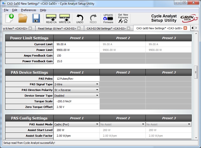
All of the Cycle Analyst setup parameters can also be configured from your computer using the Setup Utility program. The latest V1.5X releases have a button that automatically checks our servers for the latest firmware so that you can always access the latest beta and release builds too. We have made this software available on Windows, Linux, and MacOS.
Download latest CA Setup Utility for Windows
Download latest CA Setup Utility for macOS
Download latest CA Setup Utility for Linux
At the moment, these software packages do not have a conventional installer. The windows executable will extract the software package in a folder location of your choosing. With the MacOS build, you will generally need to drag the downloaded file into your applications folder in order to launch it.
Firmware Releases
The V3 Cycle Analyst firmware is in active development as we continue to refine and improve the feature set to suite the needs of technically savvy ebike users. Devices are shipped from Grin using the most recent stable release build, which at the moment is V3.14.
The most recent firmwares can be accessed by clicking the "Get Latest Firmware" button from the Cycle Analyst Setup Utility. In addition to the standard release builds, we also make available beta builds and various experimental and special purpose releases with features that aren't in the primary code.

The Beta category includes firmware that has passed our internal testing and which is ready for broader usage and potential bug detection. Most new features go through several rounds of beta releases before going in primary code and this allows early adopters to try things out.
The Solar category is for firmware intended for solar EV applications, in which the normal auxiliary input plug is used as a second current sensor. This firmware allows vehicles to monitor their consumption current separately from the solar charging current. It was developed as part of our participation in the Suntrip solar bike race but can be used in any application where two independent currents need to be monitored. The CA3-13v1S code is for devices featuring just a solar shunt and has a 10Hz fast data log rate. The CA3-13a10SG assumes that a GPS device is connected as well and outputs lat/long/elevation/time data to the log file.
The Experimental category currently includes two branches that can be of interest to users doing more advanced vehicle analysis.
The 3.13X1G code allows the CA to read and display data from a NMEA output GPS sensor, including position, elevation, heading, time etc. Normally this would be achieved with a simple modification to the GPS Analogger device by connecting the GPS's output to the CA's serial input line via the existing TRS cable. The data output stream saved by the analogger then includes a single file with synchronized position information which simplifies uploading and viewing on our trip analyzer web application.
The 3.13X1F code is the same as our standard release firmware, but the normal 5Hz fast log rate has been upgraded to a 55Hz 115kBaud option. This allows high resolution transient analysis of vehicle performance using a computer or android phone with USB OTG to log the data. In 55Hz mode, the CA will not be able to communicate with the setup software or the analogger product because of the higher baud rate, it must be returned back to 1Hz log mode to work with these products.
For each firmware version, there is a complete set of release notes and explanation of all the settings installed as .html files in the data/help directory. These can be accessed from inside the setup utility software by cliking "Help->Help" which well display the setting and release information for the currently selected firmware.

Drivers and Details
Succesful communication with the Cycle Analyst for firmware updates and bulk setting changes requires a serial communication cable, which is plugged into the TRS jack on the Cycle Anlayst. Grin offers a USB->TTL serial communications cable with a nice 3 meter (9 feet) lead length to make it easier to reach the CA on your bike from a computer. This USB cable must be recognized as a COM port on your computer in order for the software to function. In general, both windows and MacOS will automatically install the correct drivers, but if your device is having issues recognizing the USB cable as a COM port it may be necessary to manually download the Virtual Com Port (VCP) drivers from FTDI
https://www.ftdichip.com/Drivers/VCP.htm
The Cycle Analyst must be externally powered up in order to communicate, it won't get power just from the programming cable alone. So either bring a laptop nearby to your ebike, or have a battery or other source at hand to turn on the CA.
Videos
Cables and Connector Pinouts
The V3 CA has a bundle of additional wires coming out of it in addition to the normal 6-pin CA-DP plug. These are input plugs for different sensors and accessories, mostly terminated with female JST-SM connectors, and their pinout and description is in the diagram below:
PAS and torque sensors are only compatible with battery voltages lower than 52V nominal when the Cycle Analyst is providing power for the device. Connecting a PAS or torque sensor to the CA3 above 52V nominal voltage may cause damage.
New 8 Pin Waterproof Plug for CA3-WP
In 2019 we also introduced a new CA plug option based around the popular 8 pin waterproof HiGo main signal connector. The extra two pins allow us to pass extra wires for the motor temperature signal and an on/off power switch directly to the Cycle Analyst to reduce the amount of cable clutter. The pinout was chosen to be very similar to that used in Bafang and other systems that use an 8 pin main cable, only with the Tx and Rx communication wires connecting instead to Shunt+ and Shunt-.
At the moment we continue to offer CA3's in both models, but in 2020 we will switch to using the WP8 plug exclusively, and we will stock WP to JST adapter cables for those needing to mate an old CA3 to a new controller, or visa versa.

Circuitboard Pad Descriptions
If anyone wants to do their own custom wiring harness directly into the Cycle Analyst, then the following diagram shows the solder pad location for each of the sensor inputs along with a description of each pad.
Throttle In (Thi): This is the input signal for the user throttle. It can accept signals in the range of 0-5V. When no throttle is attached, the signal will be pulled down to 0V.
Temperature Probe (NTC): This is the input for a temperature signal. The pad has a precision pull-up resistor to 5V, so it can be used with a simple 10K NTC thermistor between the pad and ground. Alternately, an actively driven signal from 0-5V (such as from an LM35 type IC) can be fed to this pad and scaled linearly into a temperature reading.
Auxiliary Input (Pot): The purpose of this input is to allow on-the-fly adjustments of one of the CA's limit values (ie the current limit, speed limit, or power limit), or for switching between different mode presets. That can be accomplished either via a potentiometer, or for discrete settings with a multi-position switch and resistor dividers. A 0-5V signal range is allowed, and it defaults to 5V if left disconnected.
Digital Ebrake (EBK): This input has an onboard pull-up to 5V to be used with an ebrake cutoff switch. When the signal is shorted to ground, the CA thinks that your brake levers are depressed and can either cut off motor power, or (for controllers that support the feature) enable regenerative braking through a 0-0.8V throttle signal.
10V: This is an output pad specifically for supplying power to a torque or PAS sensor. It is a 10V bus rather than a 5V supply since some sensors (eg Sempu, NCTE, Thun) require at least 10V in order to operate. For PAS sensors that can't operate with more than 5V supplies, this voltage must first be stepped down with a regulator. Care must be taken as this supply is not fused or protected, and a short to ground will damage the CA. Current draw from this line should be limited to 30mA max and only with 48V or lower batteries.
Pedal Sensor Input (RPM): This is a digital input for a pedal cadence sensor. It has an onboard pull-up resistor, so it can work with an active hall effect device or a simple magnet and reed switch pickup.
Pedal Direction Input (Dir): This is used to distinguish between forwards and reverse pedal rotation for PAS sensors that provide this signal. It can support both a pure direction signal (eg 5V = fwd, 0V = reverse), or a quadrature type encoder such as on the THUN and TDCM sensors, and all the basic PAS sensors supplied by Grin.
Torque Sensor (Trq): This is a 0-5V input for a torque signal. The human pedal torque can be measured either via a torque sensing bottom bracket (THUN, Sempu, TDCM), or via a DIY tension meter on the bike chain itself. The torque signal here is multiplied by the calculated pedal RPM signal to derive the human power on the CA, and to provide proportional torque assist.
External Voltage Sense (Vex): The purpose of this pad is to allow for sensing high voltage batteries without the danger of bringing a high voltage line up to the Cycle Analyst. The external battery must be scaled down to a 0-5V range, and this will allow up to a 500V voltage display range on the CA (as determined by the V/V VSense value in calibration).
Serial Receive (Rx): This is a 0-5V TTL input signal for serial data communication into the CA used for reflashing the firmware.
Serial Transmit (Tx): This is the 0-5V TTL serial data transmission line. It outputs a steady stream of info (9600 baud, 8 bit) for datalogging purposes, and is also used by the bootloader to verify flash updates.
Negative Shunt Sense Lead (S-): Connects to battery side of shunt, must be within 0.5V of Gnd
Positive Shunt Sense Lead (S+): Connects to controller side of shunt, must be within 0.5V of Gnd
Throttle Over-ride Output (Thd): This is the same as the Throttle output (ThO) after passing through a diode. It is used for legacy V2 style CA connections where the CA is only used to pull down a separate throttle signal.
Throttle Output (ThO): This is the direct throttle signal from the CA, which can be connected directly to a controller throttle input line. The CA can drive this throttle output as a 0-5V analog range, or as 0-5mS pulses at 55Hz.
Speedo Pulse Input (Sp): Can be wired up with a reed switch and magnet speedometer sensor, or connected directly to one of the hall signals in a direct drive motor.
Battery Power (V+): This is the V+ supply of the battery pack, used both to power the CA and also to sense the battery voltage. The maximum supply voltage with no accessories is 150V, but this must be derated if there are other devices (Torque Sensor, Input Throttle etc) also drawing power from the CA.
Where to Order
Worldwide Shipping
Connect Now